The early cranes and hoists used hemp ropes but by the beginning of the nineteenth century most docks and larger industrial users had changed to using chains made of iron. These tended to become brittle with repeated hauling over the pulleys so the chains were taken down and annealed (heated to red heat and allowed to cool) about every six months or so.
Iron rope appeared in Britain in the mid nineteenth century (having been developed for use in German coal mines) but it did not become the norm of cranes and hoists until the latter part of the century and chains continued in use in many locations well into the twentieth century, notably on railway yard cranes. Even today chain is preferred for some applications, one notable example being the 'chain block' so beloved of amateur mechanics and in wide use industrially.
One drawback of a chain is that it gives no warning that it is about to fail, stranded rope usually starts to break visibly before failing.
Whatever the nature of the lifting machine the load has to be attached securely. Most cranes have a simple hook, but it is worth noting that designing a crane hook is one of the jobs that separates the men from the boys in the engineering world. The port authority in Liverpool in the early nineteenth century reported that over half the injuries and deaths on the docks were due to crane hooks failing but it was the later part of the nineteenth century before properly designed crane hooks became available.
From the early 1930s every crane hook had to be tested and marked with its safe working load, the details were on a separate certificate held in the office. On small hooks and other small items of equipment the marking might just be a number and the details might only be recorded on the certificate. These markings would be invisible in British N.
A common feature of crane hooks is the ball or oval of metal near the hook itself, this adds weight to the hook to ensure the cable will pay out properly. On very small cranes the operator could usually reach the hook and pull it down if required but even these small hooks might have a small weight above them moulded to the chain or rope. The hook itself usually hangs from a pivot on the weight and the ball is often painted a bright colour (red up to the 1970s, white or yellow since) to help the crane driver sight it.
With larger cranes and heavier weights the hook is often attached to a length of chain, typically three feet (1 metre) long, suspended beneath the weight so the personnel do not need to wrestle with the heavy weight when attaching a sling to the hook.
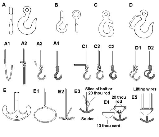
Fig ___ Crane hooks
Fig ___ A is a sling hook, the curve in the hook is designed to allow the hook to hold a rope loop securely, it also allows the hook to be hooked over its own chain. These can be made from 5 amp fuse wire as shown.
Fig ___ B is a common design with a large eye to take hemp rope, there were often used in docks. These hooks were used on cranes and also attached to lengths of chain or rope to make slings or 'snotters'.
Fig ___ C is a Liverpool hook, only used on cranes not on slings, the projecting upper part is designed to prevent the hook catching on the sides of a ships hold when a load is being lifted, it also serves to reduce the risk of the rope or chain sling jumping free if the load is jolted.
Fig ___ D shows a sling hook fitted with a hand loop, again only used on cranes, this allowed a man to release the load without risk of getting his fingers trapped under the sling.
Fig ___ E shows a ramshorn hook, used for heavy loads. The two horns of the hook meant that two heavy slings could be used without a risk of them trapping one another on the hook. This kind of hook is associated with heavy lift cranes, usually it is mounted between two triangular plates and often swivels in the mounting.
The best way I know of to make a crane hook is to use the fine wire recovered from multi-stranded layout wire (or even mains cables if they are the light duty 5 Ampere type).
First bend the wire round a pin to form the loop and make a few twists. Now form the ends of the wire as shown below, slip the hook off the pin and apply a coating of solder.
I make mine by bending the wire as shown in the sketch and adding a coat of solder to thicken it and make it rigid. The solder makes the whole thing stiff and it will actually lift quite a load if required. To finish squeeze between flat vice jaws or hammer on an anvil, this makes the hook thick in the vertical plane. The remaining long tail can then be fitted to the crane to represent the rope or chain.
Types A and B on hemp or wire ropes are easy to model using a strand from multi-stranded layout wire bent to shape, coated with solder and hammered to flatten it slightly. Bend the strand into a U (A1) shape and then wind the short end round the longer side to form the weight (A2). Clip off any surplus wire to form the weight shape (A3), bend the bottom loop into a hook shape and when happy apply solder (A4). The solder makes the hook itself rigid and fills out the ball (although this may need a little sanding down afterwards). The rope type hook with the large ring can be represented by twisting the tail of the wire into a loop (round the tip of a sewing needle) before soldering. The Liverpool Hook (C) and the sling hook with hand loop (D) can be made in a similar way to the chain hook but instead of cutting off the spare wire forming the 'ball' leave this in place and bend it to shape to form the upper projection or handle before soldering. The 'Liverpool' hook has evolved into the modern crane hook which usually has a hinged plate that rests on the tip of the hook, these can be made by leaving a longer tail and folding this down onto the tip of the hook after flattening it.
For larger cranes with big weights twist the wire from about 6mm before forming the ball of the weight, the twisted wire serves to represent the chain between the hook and the weight. The ramshorn hook (E) is associated with heavier loads and larger cranes. This time make the wire into a loop as shown then form the loop into a flat U shape and separate the two strands. Now apply solder to the horns of the hook, trying to keep it away from the strands (holding the strands in a pair of pliers helps). Now cut a slice from a 1 or 2mm diameter rod and wind the trailing ends of the wire round this to form the pulley block. This is then glued between two triangles of 10 thou card, adding scraps of 20 thou rod between the upper corners of the triangles allows you to thread 5 Amp fuse wire round these to form four lifting ropes as shown. These hooks and their associated pulleys were heavy so a weight was not usually required.
The crane hook is in turn used to suspend some suitable form of lifting gear, the notes below describe some of the more general lifting aids.
The simplest aid is the length of rope, hemp rope was generally preferred to wire rope up to the 1970s as wire rope is difficult to tie a knot in, or splice the ends of. Wire strops (a length of wire rope with a loop already spliced into each end) appeared in the 1930s but they were not common until the 1960s (these strops fall under the same legislation as the crane hooks and have to be tested and certified for a given weight).
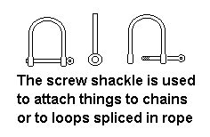
Lengths of chain were and are often used as they could be adjusted to a good tight fit using a shackle. A shackle is a D shaped metal loop with a removable pin forming the vertical part of the D, this pin passes through a plain hole in one side of the shackle and screws into a threaded hole on the other.
Fig___ Shackle
In ports where large quantities were likely to need shifting large nets were used, these allowed items such as crates or oil barrels to be lifted out of the ships holds. Where the load would suffer from such treatment 'trays' were used, notably for materials packed in cardboard cartons. The railways were not dealing with such large quantities so cargo nets and trays were not used.
The railways did make use of some lifting aids however, a standard piece of kit would be a spreader-bar, basically a heavy girder with rings at each end. The crane hook could be attached to the centre of the bar and lifting ropes attached to the rings on the ends. A spreader bar could be used when lifting steel bars and the like where a rope loop (or 'snotter') might slip along the load. They were also used to prevent the lifting ropes biting into the load.
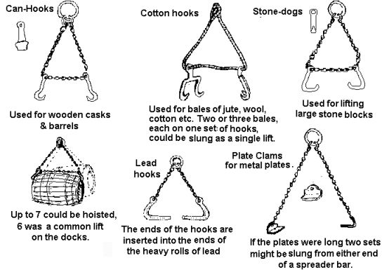
Barrels were lifted using a loop of chain with two hooks running on it. The hooks were designed for the job and were called 'barrel hooks'. These hooks had wide blunt ends which were placed at the ends of the barrel and as the crane lifted the chain loop pulled them tight up under the rim of the barrel for purchase.
Fig ___ Lifting gear for barrels, bales, stone blocks, rolls of lead and metal plates.
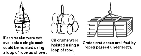
If a set of hooks was not available a single barrel could be lifted slung on end as shown in the drawing below. Barrel hooks tend to punch through the metal ends of metal drums so they should not be used (this did occasionally happen in docks however). The 45 gallon steel drums are generally lifted with a wire rope loop. This is passed round the drum and through itself, then slipped over the crane hook, up to three drums can be safely lifted in this way.
Fig___ Lifting barrels, drums and cases with rope
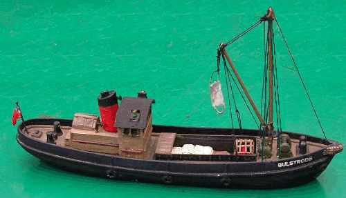
Some items used in the docks were not used by the railways, mainly because a ship might be unloading a hundred similar items whereas a railway wagon might load just one so the time and effort to use the kit out weighed its advantages. Examples include canvass slings (a strip of canvass with a loop of rope sewn along the longer sides leaving a loop at each end) used in the docks for paper sacks and bagged cargo such as wheat and 'case hooks', pairs of flat plates bearing spikes used for lifting wooden cases and crates. The model shown below has a cargo of cement in sacks being unloaded using a sling.
Fig ___ Model of a ship using a canvass sling.
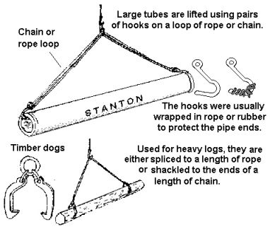
Larger metal pipes could be lifted using L shaped hooks as shown below but where the end was threaded it was common practice to use a spreader bar with a 'snotter' at each end. Small metal tubes were handled in bundles, often using a wire rope loop passed round them and through itself (as shown in the drawing of the steel oil drums). If the tubes were long the bundle might require a spreader bar with a noose hanging from either end. Clay pipes could be lifted in a similar way but these were usually man-handled in and out of railway wagons to reduce the risk of breakage. Transporting clay pipes safely was one applications for the H type railway container of the 1930s (see Vol.1 Fig ___).
Large timber baulks, tree trunks and the like can be lifted using metal 'timber dogs' as shown but telegraph poles were lifted using a chain 'snotter' (a length of chain with a steel ring on one end and a hook on the other).
Fig___ Handling pipes and heavy timber
Pit props were commonly man-handled by the railways but they could be lifted using a length of plain chain with a loop at one end and a hook at the other. The chain was laid round 10 or so props and the hook was then passed through the loop and hooked onto the crane.
Motor vehicles were usually moved on and off railway vehicles at end-loading docks or using ramps laid up against the end of the vehicle. They can be lifted in one of several ways, one of the more common methods used in docks involved metal trays under the wheels suspended on chains or wire ropes from transverse spreader bars above which in turn would be attached to the ends of a third longitudinal spreader bar suspended from the crane hook. Where the design of the vehicle allowed (farm tractors etc.) chains with protective rubber tubing might be looped over the ends of the axles.
Cars were commonly shipped by sea in wooden cases but individual un-boxed vehicles were lifted onto the ship using either two long nets a couple of feet wide under the wheels, or bars slung under the axles and suspended from cross bars so the cables did not bite into the body. The crossbars were then slung from a spreader bar, the lifting point being the centre of this spreader.