Materials Handling - Introduction
For a description of the various sacks, barrels, baskets etc used for shipping goods in Britain see Appendix One - Packaging Materials & Containers.
Depending on the end product anything from twenty to sixty percent of the cost of manufacturing is used up in moving the parts or raw materials about within the works itself. As industry has developed there has been a steady evolution of handling methods, most progress in this area began in America where labour was always in short supply up to the 1970s.
In Britain an awful lot of work was done by hand, as a result most goods were packaged with this in mind. Small trucks and trolleys for moving heavy objects, bags, drums and pans, only appeared in any number in British factories in about 1900. In 1906 someone at a Philadelphia (USA) railway station thought of adding small electric motors to small four wheeled baggage trucks so the operator did not have to pull the thing along, by the 1920s a driving platform had been added and these small runabout trucks were widely used in British docks and railways by the 1930s. They remained uncommon in industry however, part of the problem being that cobbles were commonplace and this made moving small wheeled trucks about rather difficult.
Fig___ Early electric trolley
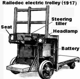
This machine had a seat offset to one side, the operator could drive in either direction with equal ease although only the small wheels under the main load bed were used for steering. These machines were used on the docks and in industry as well as on the railways.
Larger industrial establishments had internal railway systems, quite a few used standard gauge equipment but various forms of narrow gauge systems were widely used. The latter are not too difficult to model although the small wheels, typically only a foot or less in diameter, represent something of a challenge. Small disks punched from plastic card with a 'leather punch' or slices cut from the end of rod or tube can be used but mouldings made using the Graham Farish pony truck wheels, although larger than ideal, have the advantage of spoke detail. If you build a model using these wheels it is perfectly possible to fit it with couplings and actually have a works loco move it about the place.
Many N gauge modellers will only have the odd few sets of these wheels, replaced on models with alternatives from other sources, they can however be duplicated using a bar of soap and a small amount of white metal salvaged from a kit. Press the Graham Farish wheel repeatedly into the moist soap to make the moulds, the scraps of metal are placed in the hole and a soldering iron gently applied to melt the metal. When it has cooled the metal wheel casting can be washed from the soap with water and trimmed with a knife and small file. Any wheels that have not turned out well can be recycled. These home made copies will not 'roll' and can only be used for static models. Suitable bodies for most of the small wagons used for moving minerals can be made using the Plastruct 'fineline' polystyrene oblong section tubes. Those used in coal mines and quarries are considered in connection with those industries but steel works, chemical and glass factories all had a use for small wagons to move coal and raw materials about the place and a number of nineteenth century 'contractors' tipping wagons remained in industrial use into the 1960s at least.
Fig ___ Small wagons for factory use
The conveyor belt appeared in the later eighteenth century, an early use was in the coal mines where freshly mined coal was tipped onto the belt to allow bits of rock to be removed (these were called 'picking belts'). One of the first manufacturing applications was in the Royal Navy's biscuit factory in Deptford in the first years of the nineteenth century. The overhead 'monorail' carrying suspended loads has been around since the early nineteenth century, the technical name is a 'trolley conveyor'. First developed in Manchester in the 1830s for use in cotton mills they were adopted by the large meat packing works around Chicago in the 1860s and 1870s. Later as electric motors became available these packing plants added powered drive to the conveyor.
Mass production using an assembly line was originally developed by the British Royal Navy, mainly for the making of pulley blocks for their ships. At the time the Royal Navy was the only enterprise large enough to justify the investment but the benefits soon became clear as productivity rocketed.
In 1901 Ransome Olds (maker of the Oldsmobile) introduced mass production and the assembly line. In 1909 Ford decided to make only one type of car, the Model T, to make the greatest advantage of mass production. This proved extremely successful and most motor manufacturers reduced their ranges to only one or two models.
In 1913 Henry Ford took the conveyor belt from the Royal Navy biscuit factory, added the power drive from the Chicago meat packing industry, mated these with the production line idea in use at Oldsmobile and introduced the conveyor belt motor car assembly line (he had tried them out on the assembly of dynamo's first). Ford soon demonstrated the benefits of the powered moving assembly line, where the workers and their equipment remain stationary, but it was the 1920s before they appeared in any numbers in Britain and it was the later 1930s before they became commonplace in British industry.
Mass production requires a mass market, it was only with the arrival of the railways that goods could be distributed to such a market. By the later nineteenth century mass production was a fact of life, spurred on in part by the American Civil War where the combination of massive demand and shortage of skilled man power produced an unprecedented investment in automatic machinery. The key to mass production is the movement of materials efficiently and the key to this is the powered conveyor system. Prior to the arrival of reliable steam power this meant either gravity or water wheels, both of which have their limitations. The railways provided a market that fostered the development of the steam engine and the 'boiler house' became a standard feature of the majority of factories.
Conveyor Systems
The four main types of conveyor are the bucket conveyor, the screw conveyor, the moving endless belt and the 'trolley' conveyor where the goods being moved are suspended from an overhead rail.
The bucket chain type consists of small buckets suspended between two loops of chain, the buckets could swing so the chains could be taken upwards or horizontally. A tripping plate can be mounted to empty the buckets automatically (this plate could be moved along the line, allowing different hoppers to be filled). The bucket type of conveyor was used by the ancient Chinese a couple of thousand years ago and first appeared in British industry in the 1840s when it was used for grain handling.
One use for a bucket chain conveyor is where road vehicles deliver to a rail loading hopper but where the lay of the land does not allow them access to the top. The truck backs into a covered area and empties its load into a hopper which feeds the moving buckets which lift the material and deposit it into a silo. These facilities take up little room and have been understandably popular with modellers.
The next oldest is the screw conveyor or auger, supposedly invented by Archimedes this uses a screw thread in a close fitting tube. As the screw rotates the material moves along the tube, this simple machine can lift and lower liquids, powders and granular materials as well as transport them horizontally. These are mainly used for powders and granular materials, discussed in the following section.
The trolley conveyor became practical as iron and steel rolling technology evolved, as noted above trolley conveyors appeared in the Manchester cotton mills in the early years on the nineteenth century, capitalising on technology being developed for making railway rails. Adding a chain drive allowed the mechanisation of the system and they remain today an intrinsic aspect of industrial production.
The belt type conveyor requires a suitable material for the belt and before reliable rubberised cloth belting was available there were belts made of interlocking metal plates which could carry minerals. British coal mines were using short 'belt' conveyor belts made of old winding ropes in the 1860s, these were used so staff could pick out stones and other unwanted material and were known as 'picking belts'. In America early hay lifting conveyors using jointed metal belts were being seen in the fields at about the same time and soon appeared in Britain. Other options for this kind of system inside factories include chains with wooden or metal battens between them. It was the mid 1920's before rubberised fabric was developed to the point where it could be used to carry bulk minerals reliably. As the technology improved conveyor belts became longer and able to carry heavier loads, by the 1950s they were replacing narrow gauge tipper wagons in industries such as aggregate quarries.
On the railways conveyor belts became a feature of railway 'sundries' handling in the 1930's in the major city depots. In the post war era British Railways invested heavily in this technology in all the larger sundries depots, dramatically reducing the number of sack trucks and trolleys used in these depots.
Belt type conveyors operating outside are often covered, not to protect the cargo from the weather so much as to prevent dust being blown off the belt. The covered conveyor makes life much easier for the modeller. One thing to watch is that conveyors are usually operated between the horizontal and about thirty degrees, anything steeper than that and the material tends to roll back down the slope. The maximum incline of a conveyor is governed by the natural angle of repose of the material to be moved. The angle of repose is the steepness of the pile it forms if you tip it in a heap. For lifting material from the vertical down to angles of about forty five degrees a bucket chain type conveyor would be used.
Conveyor belts can stretch for considerable distances but two conveyors sometimes meet, this is required where the maximum length of a single belt has been reached, a corner has to be negotiated or where the belt feeds into a bucket chain lift feeding a high hopper. Where conveyor belts meet the bottom of the belt system on the input side is always higher than the top of the belt on the output side.
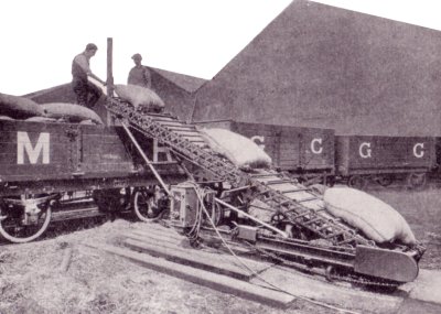
Small mobile belt conveyors have been in use since the 1920s, they were used in larger railway goods yards to load materials such as boxes or bricks from ground level into open wagons. They are also used to pile coal into stockpiles and to load road and rail vehicles with bulk minerals. The American coal merchants made extensive use of portable conveyors, American accessories ranges include a number of these small machines all of which can be used on a British layout.
Fig___
Portable conveyor used in a goods yard
A simple mobile conveyor can be made from plastic card, the longest unsupported length for a mobile conveyor would be about 30mm, longer conveyors would need some additional support along their length. Cut a strip of 40 thou card 3mm wide and as long as is required. Conveyor belts used for minerals have a characteristic dip in the centre running along their length, you can add strips of 20 x 20 thou card and sand these down or just wrap some sand paper round a beer tin or something similar and use that to sand a shallow channel into the top face of the strip. Sand paper the upper end of the strip to a rounded profile representing the end roller. For the belt itself cut a strip of 5 thou card about 2mm wider than the heavy strip, and glue this to the top of the heavy strip, forming it with your fingers to follow the hollow centre Cut a lot of 1mm lengths from a strip of 20 or 30 thou microrod, trying to make them as even as possible, and glue these under to the underside of the 'belt' at 1mm intervals. This gives the impression of the rollers. Finally take a length of 5 thou strip and glue one end to the top end of the conveyor at a slight angle. This strip will be cut to length and glued to the lower end when completed to form the portion of the belt 'hanging down' under the conveyor. The support for this belt can take many forms, from a simple light tubular metal frame with a small petrol or electric motor attached (as used in the 1920s goods yards) to a substantial four wheeled trailer with a hefty motor and a large hopper. These latter are used for transferring minerals directly from rail to road using a raised length of track to allow the rail wagons to discharge into the hopper. A variation on this was the over-rail-under-loader, which had a low mounted hopper feed that could be manoeuvred under a railway hopper wagon to allow coal deliveries to yards lacking any form of coal drop.
Two variations on the conveyor are the single 'bucket', 'skip' or hoist running up from the wagon tippler and able to hold a full wagon load, the other is the wagon hoist where the wagon itself is lifted and tipped into the top of a hopper. Both these systems are most commonly associated with railway locomotive coaling stages (the LMS seem to have been rather fond of this arrangement) but it was also used in some industrial applications, notably for 'charging' blast furnaces. In the iron or steel works the hoist was usually an open metal framework with a 'lift' inside. The container might be a simple bucket, hinged so it could tip at the top, or they might use small wagons to transport the minerals and take these up the tower for tipping.
The final variation is the aerial rope way, technically a cross between a belt conveyor and a trolley conveyor. Messrs Bullivant & Co. Ltd. of London developed a flexible form of wire rope in the 1870s which allowed this kind of conveyor to be developed, by the 1930s the world leader in building these was British Aerial Ropeways.
There are five basic types of aerial ropeways-
1. The endless running rope, with carriers hanging from it on simple hooks.
2. An endless rope, with the carriers rigidly fixed in position on the rope.
3. The single fixed rope, in which one carrier, hanging from a fixed rope, is drawn to and fro by means of an endless hauling rope.
4. The fixed rope, in which the carriers are drawn along and hang from a fixed rope which acts also as a rail, returning on a parallel rope.
5. The use of two fixed ropes with an endless hauling rope, in which one carrier travels in one direction, while the other travels on a parallel rope in the opposite direction. This is a serviceable type of ropeway, capable of being used over extremely long spans, and of carrying loads up to several tons.
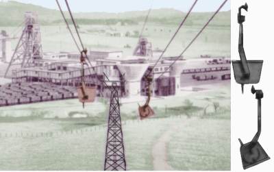
Wire rope is specially suited for aerial' ropeways for conveying ore, metals, merchandise, & etc., over ground where it would be difficult to arrange transport by ordinary means. These aerial ropeways were often used at larger collieries to transport spoil to the 'slag heaps' (the running cable carries a series of suspended buckets held in simple stirrups, at the discharge end a simple mechanism releases the buckets so they tip downward and empty).
The example below is from a National Coal Board leaflet and was photographed in the later 1950s, shetched at the side are the tipping skips carried on the cables.
Fig ___ British coal mine photographed in about 1950
Ropeways make an interesting feature as the suspended buckets can be made to move. Unfortunately the buckets usually visibly hung down after emptying, the best option would therefore be to have two loops of 'rope', one carrying full buckets, the other the empties. These can be motorised to give the impression of working although both ends will need to be disguised to hide the drop below the baseboard for the return trip. This is not essential, when I used to visit a relative who lived close to a coal mine I never saw the buckets actually moving although the mine was in production at that time.
^
Go to top of page
International Good Guys ~ Making the world a
better place since 1971 ~ Site maintained by

All material Copyright © Mike
Smith 2003 unless otherwise credited