Note - This section provides a general introduction to various types of crane and modelling options. Dockside cranes are discussed and illutrated in the section on Lineside Industries - Canals, docks, harbours and ship types. The smaller mobile cranes used by the railway companies are discussed in the section on Railway Company Goods Facilities - Goods Yards and Facilities, cranes used for container handling are discussed in the section on Railway Company Goods Facilities - Container handling.
For lifting heavy weights you need a hoist or crane. At its most basic a hoist is a fixed point from which a pulley block is suspended. Hoists were and are used on the outside of warehouses feeding outside doors at the various floors, this meant no room inside was taken up with a lift or elevator. Probably the most common form was a simple wooden beam or length of girder mounted in a wall above a doorway or opening. This is technically called a 'cat head', the term coming from sailing ships where such a support was rigged to lift an anchor whilst keeping it clear of the ships side.
The girder type had the advantage that it could form one end of a trolley conveyor with the pulley block mounted on wheels running on the lower web. When the load had been hoisted to the top it could be pulled inside still suspended from the block.
Some hoists resembled small cranes bolted to the outside wall of a building, these are more usually associated with warehouses. In some cases the hoist was housed in a simple wooden structure, resembling a dog kennel sticking out of the wall above the access doors. Where the loads being handled might suffer from the weather the hoist and the associated doors on each level would often be boxed in for the full height.
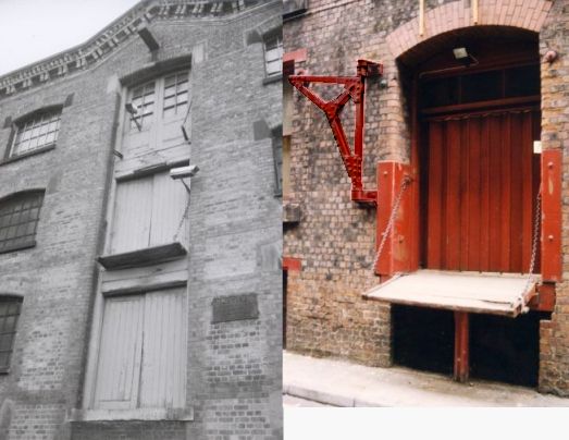
Often hoists had no gearing at all, just a simple pulley and a rope. this was not usually a problem before the 1960s as most loads were designed to be man-handled anyway. A set of block and tackle increased the load which could be lifted although this slowed the job down. Not all hoists were mounted high up on the building, in the example shown below right the hoist is used to get heavy cases into a street level entrance, note the steel plates to protect the brickwork. Inside the building there was a lift, the building has a hipped roof so the lift motor is inside the roof space. Where the roof space was used the lift motor room would be elevated in the form of a short tower on the roof.
Fig ___ Hoists
The larger the lift the larger the motor room needed to be. The old Ford motor car factory in Stockport dates from about 1910, a three storey building with a lift inside large enough to move a car between the floors. The building is a plain rectangular structure with square multi-pane windows, the steel frame is clad in concrete, forming a visible grid on the outside with brick in-fill. The lift motor room on the flat roof is about fifteen feet long by eight feet wide and about eight feet high.
Hoists lift loads up the side of a building, where a building is not available an alternative is the sheerlegs. The most basic sheerlegs is an inverted V shaped frame with the pulley block suspended from the apex. Adding a third leg makes a stable structure capable of lifting heavy weights and this was often seen at railway maintenance depots to lift engines and rolling stock to allow the wheels to be changed.
The legs of the sheerlegs can be various kinds of box section metal but timber was probably more common. Tripod type sheerlegs are usually fixed in position, they can only lift vertically, but they are good at handling heavy weights and they are simple to erect for a one-off job. In docks where ships are repaired or where very heavy items might be moved a sheerlegs could be mounted on a large barge. In this case the sheerlegs remained fixed in position but the whole barge could be moved about to position the load. A two legged sheerlegs has the advantage that the frame can be swung, allowing a load to be both lifted and moved.
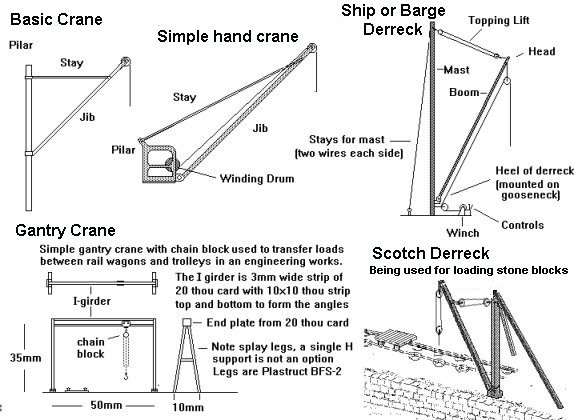
If you need to do more than a vertical lift you need a crane or derrick. The basic crane has three basic elements, the pillar that supports the machine, the jib that carries the load and the stay that holds the jib up. Such a basic crane can move a load from side to side (called 'slewing'), posh cranes can move the load closer to or away from the base of the crane by raising or lowering the jib, called 'luffing' or 'derricking'.
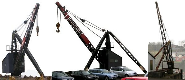
A derrick is technically any crane with a tall pillar and capable of luffing (and possibly but not essentially slewing). The rigid 'stay' is replaced by block and tackle to permit luffing and this type of crane is usually associated with ships and barges. One problem with the derrick is that the base of the jib will exert a sideways force on the gooseneck (hinged joint) when it is slewed (ie pulled round to the side). A logical development was to mount the mast or pillar on a turn-table so the jib was always pressing squarely against it. This is known as a 'scotch derrick', the examples in the photos below are both still in use handling canal barge lifts in Northwich (in Cheshire, on the River Trent).
Fig___ Scotch Derrick types
The 'Scotch Derrick' was common in quarries, often seen in scrap yards and frequently used in the pre World War Two construction industry. They might be hand cranked or steam powered with a vertical boilered steam engine mounted on the turn-table at the foot of the mast. The heavy example shown below would typically have wooden strips nailed to one of the supporting struts to allow a man to climb to the top and grease the iron or steel pivot on top of the pillar. On some heavier examples the jib or boom could not be luffed and on these there would also be wooden strips added to allow access to the lifting pulley block.
For regular heavy work the 'gantry' or 'bridge' cranes have been used since the 1850s. These consist of a length of track raised above the working area, this is the bridge or gantry itself. A small trolley runs along this track and the load is suspended from this. The gantry crane comes in two forms, on some (such as the simple 'trolley conveyor' type shown in the sketch) the gantry itself is fixed in position and only the trolley moves, on others the gantry itself is mounted on rails and can be also be moved (when it is usually called the 'bridge'). When set up outside gantry cranes were mainly used to move heavy loads but the same idea was also used inside buildings and factories.
Fig___ Crane types
The most basic gantry crane is an I girder with a truck hanging from the lower web, the truck would have a hook slung underneath and a 'chain block' might be suspended from this to lift the load. A chain block is a set of pulleys sometimes with interior gearing, operated by a long chain which hangs down in a loop. One end of the chain is fixed to either the upper or lower pulley and the load is suspended from a hook fitted on the trailing end. The I girder could be supported by legs at either end and in a building it could be suspended from the roof or walls. Technically if the thing was mainly used to move things about the place it was an overhead or trolley conveyor rather than a crane. This system had many advantages, for one thing the girder could extend through the top of a doorway, forming a cat head and allowing loads to be maneuvered to the outside of a building (this arrangement was quite common in small industrial workshops). If the projection was greater than a foot or so the end of the girder was then commonly supported by a pair of additional iron bars in a V configuration, bolted to the outside wall and if more than about four feet legs and a top support would be added.
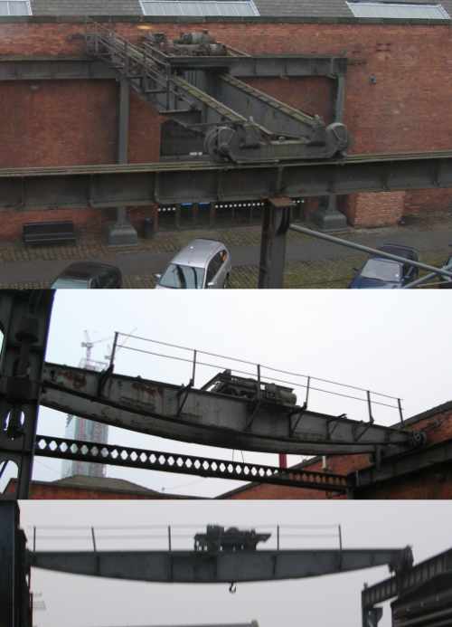
The larger machines where the 'bridge' itself can move are often called travelling cranes and broadly speaking these tended to be large machines when mounted in the open.
A typical example in a railway goods yard would have two rails, usually mounted on top of I girders, supported on a row of posts to either side of one or more railway tracks and roadways. Running between these would be the bridge with a four wheeled truck running on the top, the lift cables extending down through a slot in the bridge. The lifting power might be supplied by a separate engine but it makes more sense to have the engine on the trolley. Steam engines were sometimes used for large outdoor gantry cranes (which appeared in the 1850s) but the introduction of the electric motor in the 1880s really allowed the development of these cranes.
Fig___ Travelling crane used in a goods yard
A further variant is the cantilever crane, which has a jib that extends to the rear of the pillar carrying a counterweight, this means the pilar does not need to contend with forces trying to bend it over and can be of much lighter construction. The modern 'building site' crane is a cantilever type but the principle has been used for many years on smaller machines. Ground mounted cantilever cranes have a small footprint and do not have the long diagonal jib, making them attractive in crowded locations such as goods sheds. The example below is based on a tracing of such a crane in a rail-canal transfer shed operated by the GWR somewhere near Birmingham. Note the operator is standing on a small platform attached to the pilar of the crane.
Fig___ Cantilever electric crane used in a rail-canal transfer shed
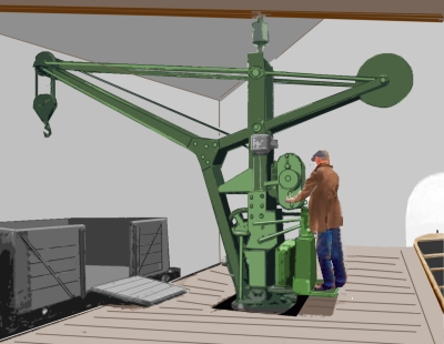
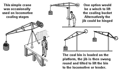
The crane on the coaling stage on Peter Denny's pre-grouping era 'Buckingham' layout was of the cantilever type and I built a simple bent-wire example (I think I used a couple of paper clips) based on an illustration of that model. This is not difficult to model from wire and makes for something a little different on a layout. The design permits two modes of operation, you can have a hand crank to lift the load or you could hinge the entire top section so that it can be tilted to lift the load. You would probably still need a pulley or two to give the operator some mechanical advantage but there are applications where this approach has advantages.
Fig___ Cantilever crane
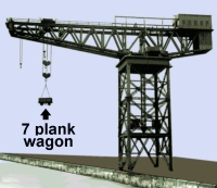
A very large preserved example of a cantilever crane can be seen in the former Glasgow docks where it was used to lift very heavy items such as railway engines and the like on and off ships. Most larger dockyards had a crane of this type, they were also occasionally used for odd jobs such as tipping coal wagons into ships bunkers, which is really using a sledgehammer to crack a nut.
Fig___ Dockyard cantilever crane
The dockyard cranes are very big indeed, and I would doubt many people would have room for such a crane on a layout, however smaller versions were also seen at various wharfs which were essentially the same shape. These were used where regular heavy lifts were required, such as emptying coal into barges, unloading iron ore and the like.
Hand operated systems are cheap, inherently simple and robust, they remained common up to the 1960s or early 1970s. The limitation of a hand powered lift is not the strength of the man or men, gearing allows a man to lift anything up to a few tons in weight. The problem is time, as a rough guide a man operating a geared hand lift can lift a ton about two and a half feet (75cm) in a minute. Two men with a standard hand-operated yard crane could lift the standard 1930s wooden railway containers on and off a wagon in perhaps ten minutes, which was fast enough for the day.
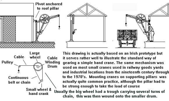
Common hand cranes in railway goods yards were mounted on a turn-table so the load can be swung horizontally but in many the jib could not be raised or lowered. This type of crane is simple and robust and as well as being common in railway yards they were often seen mounted on the outside of warehouses where they were used to transfer heavy loads from road vehicles into buildings. By fitting the ends of the stays with chains the angle of the jib could be adjusted before starting work and this was common on hand operated rail-mounted cranes. A small hand crane attached to the outside of a building is shown in the sketch below. This crane has basic gearing provided by the continuous rope or (more likely) chain running between the small and large wheels. The operator has to make many turns of the hand crank to achieve a single turn of the large wheel, the cable winding drum is on the same axle as the large wheel and revolves with it. Such a crane could probably handle loads of up to about two tons.
Fig___ Simple yard crane
Where traffic flow meant that a steady flow of loads likely to be greater than a hundredweight or so (about 51 Kg) would be expected some form of power assistance was often added. Powered hoists were also a regular feature of busy warehouses such as those found at the docks or alongside the canal.
Up to the mid nineteenth century water wheels were often used to power cranes and hoists but more common from the 1850s was the hydraulic hoist. This was developed by Sir William Armstrong (a lawyer turned inventor living in Newcastle) and consists of a piston and cylinder connected to a pressurised water supply, the movement of the piston is amplified using a series of pulleys. By fitting the pulleys directly to the end of the piston and cylinder you get a compact self-contained device called a 'jigger'. The pulley system amplified the distance the lifting rope moved for a given movement of the piston, this also meant that the load moved up or down a lot faster than the piston.
Armstrong's firm built the first hydraulic cranes on a Newcastle quayside in 1846, using water supplied from the local water mains. To get round the problem of low mains water pressure Armstrong invented a water storage tower, called an 'accumulator' in 1850. This consisted of a tall tower containing a water tank with a weighted piston mounted at the top. A steam engine pumped the water into the tank and the weight on the piston provided the pressure. These towers were often the tallest structure around, usually brick built and square in form with a slightly bulbous top section reminiscent of a very tall clock tower but without the clock. Height was useful but not essential, at the former LNWR goods warehouse in Stockport the main building is four stories high but the accumulator tower is only about two and a half stories high, this placed it above the jiggers mounted in the base of the walls. The associated pump house is a small building about twelve feet square with a pyramidical hipped roof and a sturdy square section chimney about twenty five feet high beside it. The hydraulic hoist was quick-acting, cheap to build, easy to maintain and inherently reliable. They remained in regular use, particularly in docks, into the 1970s (there are still some in use around the world today).
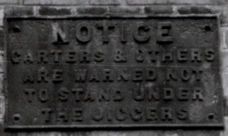
The actual design of the jigger varied depending upon the intended use, where they powered hoists on tall warehouses they could be built into a slot in the wall and were often exposed. Health and safety was less of an issue when these were built, the only protection the workers had was a cast iron notice mounted on the wall. The sign below can be seen on the wall of the building shown above under 'hoists'.
Fig ___ Warning notice mounted by a jigger
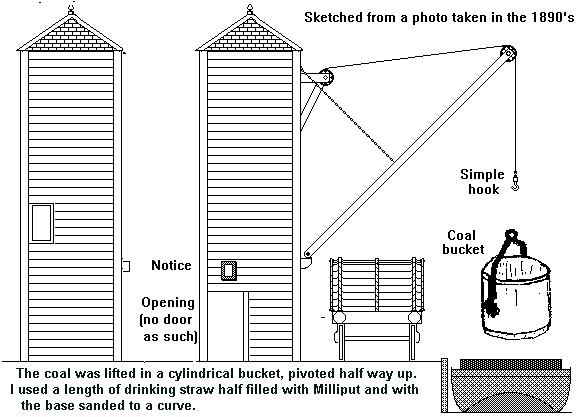
The simple 'bicycle pump' type of jigger could also be used for dock side cranes, although as far as I know it was only used for stationary (and tall) types. The coal derrick shown below was one of a group of similar cranes arranged at intervals along a wharf at Poplar Docks in London (on the North London Railway, later part of the LNWR). The basic structure is eight feet square, the rear wall and the side not shown were plain and the structure is twenty one feet tall from the ground to the eaves of the roof. The walls are heavy planking (2mm scribed card would do in N) with heavy corner posts (represent these with 2mm wide strips of 10 thou card). The roof is slate with lead flashing on the corners. The simple coal bucket was the standard way of unloading coal from small ships and barges, they were about four feet deep and three or four feet in diameter.
Fig ___ Hydraulic derrick on a coal wharf
I have seen a 7mm scale model of a broadly similar but rather more heavily built machine that I understand was used in one of the Northern industrial towns to lift loaded coal wagons from the quay to empty them into waiting barges, as I understand it the wagon was hoisted using a geared spreader bar which then tipped it on end (to about 20 degrees) to empty it. This allowed the wagon to be lowered down into the barge to reduce the breakage of the coal as small coal and dust was less valuable than big lumps. Similar tipping arrangements are available today for use with containers, notably those used for shipping coal.
When used for mobile dockside cranes the jigger was often arranged with one set of pulley wheel atop the ram and two sets mounted to either side of the base, resulting in a distinctive squat pyramidical shape associated with the common dockside hydraulic cranes (see Lineside Industries -Canals, docks, harbours and ship types). These cranes had to be connected to the hydraulic main to operate so they could not move along the quay when in use. They were however simple, reliable and easy to maintain. Examples were still operating in some remote ports into the early 1970's
To extend the reach of a crane, how far out it can lift, you can add an extension to the end of the jib. There were various occasions where this was useful, notably in confined areas such as a quarry cutting under an overhang of rock. The sketch below shows a typical arrangement, this was intended to be used with a steam winch but I am not sure what it was for.
Fig ___ Jib extension on a scotch derrick
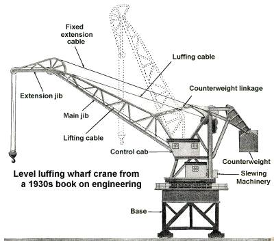
By linking the extension to the main jib (in the example above there is a rigid tie-bar between the top of the pillar and the end of the extension) you can arrange for the load to remain at about the same height as the crane jib is luffed, that is if you lift the main jib the load moves closer to the crane but remains at the same level. This was common on dockside cranes, although the example shown below, taken from a 1930s book on engineering, is a very large crane, probably based on one at a ship yard rather than a quay. These are known as 'horses heads', at least by sailors.
Fig ___ 'Horses head' jib extension on a wharf crane
Dockside and wharf cranes are more fully discussed in the section on Lineside Industries - Canals, docks, harbours and ship types.
Modelling Cranes
The jib is generally the most difficult element of the crane to model but there were some simple types. The easiest to model in the basic wooden pole, as used on derrick type cranes and some rail mounted and fixed hand cranes. All that is required is a rod or square section strip of suitable thickness with a support for the pulley on the end. The easiest way to make one of these is to use a needle of suitable length with the tapered point cut off and the 'eye' cut down to form a V. The pulley support was usually in the form of a metal cap with a socket for the pole which can be represented by wrapping a 1mm wide strip of paper round the end close by the V. The pulley wheel can be represented by cutting a small disk from 20 thou plastic card, or even postcard, using a leather hole-punch.
An alternative is to use a length of H section girder with the pulley set into the end. The H section can be Plastruct Fineline and the easiest way to make a pulley for the end is to cut a short section from the end of a small diameter bolt. The bolt diameter should ideally be slightly larger than the height of the H section, the bolt thread represents the pulley rather well and all you need to do is cut a slot in the web at the end of the girder and Araldite this in place. This can be used on quite small cranes and also on some larger Victorian designs such as the heavy fixed dockside crane shown in Lineside Industries - Canals, docks, harbours and ship types.
The A frame jib is probably the most common type on small cranes, but most people are put off by the triangular bracing between the sides. This is actually not a problem, there were several cranes which had no diagonal bracing, a few with just a couple of horizontal cross bars and one or two with a series of metal plates. I have made several crane jibs from metal, personally I use a strip of thin copper sheet to form the base plate (sold in electronics shops as 'earthing strip'). I have used a variety of materials for the jib, the simplest was a paper clip hammered straight and folded back over a slice cut from a small diameter bolt to form the pulley.
One advantage of using metal for the jib is that you can bend the upper end slightly, a feature which many small cranes had. The bottom ends of the jib can then be soldered or Araldited to the base plate and the jib cross members can be added from thin copper sheet or even from lengths of gummed paper strip. Araldite a drawing pin to the under side to act as a pivot (add the pin after soldering the jib and any other metal parts to the top!).
To represent the fully triangular trussed crane jib the best bet has to be an etched fret and for some types, such as the tall derricks used in quarries, we can make use of the etched lattice signals masts produced for OO modellers.
Since this chapter was originally written Ratio have introduced a plastic kit containing parts for a selection of LNER lattice truss signals. This kit is very useful, containing two tall tapering masts (97mm and 82mm long), two square section masts for the support of junction or bracket signals (70mm long but with a 17mm solid section on two sides), three small 'doll' masts to mount on the brackets (two at 30mm and one at 42mm length) and the associated warren-trussed supports for the brackets. Also included are signal ladders which can serve as hand rails and lengths of thin stiff wire intended for making working signals.
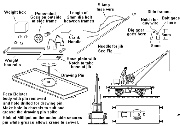
Hand powered cranes mounted on railway wagons were quite common on the railways, they were sometimes used in docks but less often seen in general industrial use. There is a preserved example at the Liverpool Albert Dock Museum and a suggestion for a simple home-made example is shown in the drawing below. There are very good hand cranes available in kit form but if you are short of cash this would serve as a crane absorbed from some minor line in the 1923 'grouping'. For simplicity the jib is the darning needle type described above and the side frames are 8mm squares of 30 thou card trimmed to the approximate shape shown. The base plate is a rectangle of 30 thou card with a notch cut into it for the jib, this is then Araldited to a drawing pin to act as the pivot. The end of the jib sits in the notch and will rest on top of the drawing pin, a generous blob of Araldite will secure it and if you wish you can add scrap disks cut from 1mm dia rod to each side to better represent the pivot. Once the jib has set in position the trailing ends of the fuse-wire stays are looped over the notches in the side frames and then wound round the stay for about 5mm to represent the adjusting chains (a smear of super-glue or Araldite will secure these in place). The hoisting drum is a short length of 2mm diameter bolt glued between the frames and the large gear wheel on the out side can again be represented by a press-stud or spoked wagon wheel. To avoid having to make the large wheel you can encase it in a protective casing, this was quite common in industry, less so on railway equipment (railways were exempt from the Factory Acts until the 1960s). Rail mounted hand cranes usually had long extensions at the rear to support a counter-weight box. The box was mounted on wheels and could be positioned to help balance the load on the hook.
Fig___ Simple rail mounted hand crane
The same design but without the weight box and its associated runners would serve for a small ground mounted yard or canal-side crane.
British Railways devised their own design of hand crane, on which didn't have a counterweight as such, instead the crane was secured to a heavy chassis which could in turn be clamped to the rails. Fleetline offer a model of this British Railways standard hand crane, mounted on its distinctive drop centred wagon.
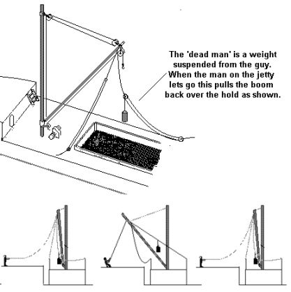
Before considering the scotch derrick It may be useful to consider the ship or barge derrick, as with the sheerlegs the hoisting pulley is not mounted in the end of the jib but suspended from it. Sailing ships had masts so rigging a derrick was relatively easy, and with the change to steam propulsion purpose built masts were added to allow the fitting of derricks and they remained pretty standard on cargo ships into the 1970's. Ships derricks are used to move things between the quay and the ships hold, neither of which move during loading and unloading operations. This means you can rig a pair of derricks with one plumbed over the ships hold whilst the other is fixed over the jetty and with the lifting ropes of both attached to the load. This arrangement, called 'union purchase', made the derrick as fast if not faster than cranes for the repetitive job of unloading a ships cargo. Where only a single boom was available a weight could be suspended from one of the guy lines. A man could use a rope to swing the derrick one way and when he let go it would return to a position determined by a second guy rope.
Fig ___ Derrick Crane using a 'dead man' for slewing
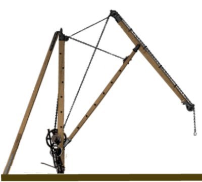
The scotch derrick has a rotating pillar and has two rigid supports fitted to the swivel at the top.
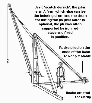
By adding two horizontal legs between the ends of the diagonal supports and the base pivot a handy portable crane was produced, this was the most common type used in quarries and scrap yards. The Scotch Derrick came in a wide range of sizes from the small hand operated example shown above to much larger machines powered by steam or (since the 1930s) by electricity. In use it was standard practice to pile rocks or other forms of weight on the ends of the outriggers, in scrap yards these were often quite large and mounted in fixed positions with the outriggers anchored into the ground.
Fig ___ 'Scotch' derrick as used in quarries
The jib and support framing can all be represented using 30x30 thou strip, the pillar is two strips of 10x20 thou with a 1mm length of 20x20 thou at the top to represent the pivot and a couple of 20x20 thou lengths lower down to set the width. The hoisting drum can be represented by a short length of threaded bolt and the gearing can be represented by adding a very small press-stud or cast metal wagon wheel to the opposite side from the crank handle. For the large types the Ratio signal mast makes a suitable jib although these were usually powered. Steam was the norm up to the 1950's with electric motors and later pneumatic motors appearing in the later 1930's. The smaller steam powered scotch derrick is not difficult to model and the same basic layout of boiler, pistons and hoisting gear was also used in other small steam cranes. Note the steam scotch derrick would probably have used trussed metal frames for the base legs, these can be represented by taking a length of Plastruct 'I' section (BFS) and drilling holes at intervals along the central web.
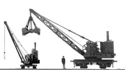
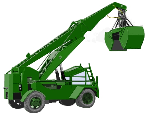
Steam powered cranes usually employed a simple vertical boiler, including both scotch derricks and steam cranes mounted on railway wagons. In the latter case the steam engine would usually also supply power to the wheels. One advantage of the self-propelled steam crane was that it could also be used to shunt small numbers of wagons about the place and they were relatively common in larger wood yards and stone masons yards. These came in a range of sizes, the examples below were both used by railway companies to unload coal from barges, transferring it into railway wagons. The smaller crane was used with a steel 'coaling bucket' but the larger crane was fitted with a grab (based on a photo taken in about 1910). Both examples were photographed before World War One, by the 1920s such cranes often had a simple wooden or corrugated iron 'body' over the boiler and gearing. The smaller type was often run onto a short length of track, slewed off to one side on the quay, the siding then being re-run beside it so wagons could be pushed past the crane and loaded one by one. The larger crane was used by the L & Y Railway, the photo the sketch is based on shows it on the same siding as one of that companies large end-door wagons (see also Kitbashing - L Various types of 12 foot wheelbase vacuum braked Lancashire and Yorkshire Railway wagons). The figure shows the scale of both cranes.
Fig ___ Medium and large railway owned steam cranes
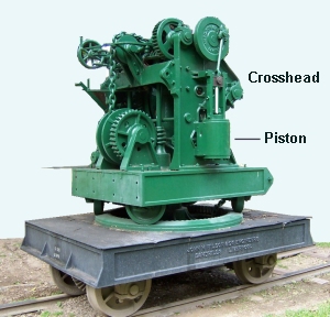
Small self-propelled steam cranes as shown above left often had their axles supported between the wheels so use two sets of 'pony truck' wheels when building the chassis. If you have replaced the pony truck wheels on Graham Farish locomotives the Farish pony wheels can be used for the crane. There is a preserved example of a simple self propelled steam crane at the Liverpool Albert Dock Museum (see photo below).
The photo below shows the 'works' of a small steam crane on a narrow gauge line in Venezuela. The crane is a standard British machine dating from before the First World War. The boiler has been removed (that would have been on a base plate on the left) and the jib is missing (from the right) but this shows clearly the piston and gearing. There would be another piston on the far side. Photo courtesy and copyright Natale Marchiano.
Fig ___ Small steam crane minus boiler and jib
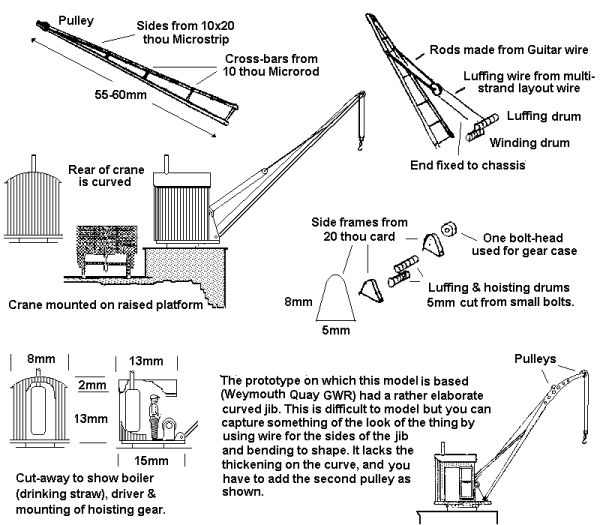
Similar steam cranes were also used in fixed installations, these were often identical to the mobile time other than for the mounting. The example sketched below is based on one mounted on a small quay, handling fruit imported from the Channel Islands. Similar steam cranes were sometimes seen in larger railway goods yards mounted on loading banks or (more commonly) on a small plinth, raising the base of the crane to about the floor level of the wagons (inside buildings the cranes would be electric or hydraulic).
Fig ___ Small steam crane
The railway companies made extensive use of large rail-mounted steam cranes but these were seldom used industrially. A model of a railway 'wrecking crane' is available in N from Fleetline but this has a cast jib which would benefit considerably from a scratch-built open webbed replacement.
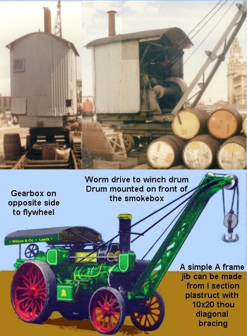
At docks and in wood yards, where heavy loads had to be regularly moved over short distances, the small self-propelled steam crane was a useful piece of kit. The example below top is a steam crane formerly used in Liverpool docks, the track used was not fixed down and could be dragged into a new alignment if required. The photographs were taken in the mid 1970s at the then new Liverpool Docks Museum. Obviously if a works had its own internal railway a crane could be built onto one of the railway locomotives and this arrangement (usually with the crane fitted over the 'cab' end of the loco) was common in steel works. Unfortunately most loco mounted cranes featured an open cab which (in N Gauge) is where we hide the motor. An alternative seen in larger works or quarries where heavy items were regularly moved was a traction engine equipped with simple cranes of various kinds. Probably the most common was a front mounted crane, powered by the cylinders used for propelling the vehicle using a clutch and worm drive as shown below bottom.
Fig ___ Mobile steam cranes
From the late 1920s small petrol engines became available which allowed the building of petrol powered cranes.
There were two basic approaches, either take a lorry and add a crane in place of the load area or build a purpose designed mobile crane (which tended to be smaller). The examples shown below date from the mid 1930s (left) and the mid 1940s (right), both were used by railway companies. The double A frame design as shown on the left was a common basic approach, this is quite a large version but rather similar smaller cranes were also built. The sketch on the right is based on a tracing of an LMS owned Hyster crane, supplied immediately after the war (possiby war surplus), this is still a cable operated crane and note it uses chain not cables for the hook. Either of these cranes could lift a three ton container on and off a wagon and examples of both lasted into the 1960s.
Fig ___ 1930s and 1940s small mobile motor cranes
By the early 1930s motor lorries equipped with petrol engined cranes were in regular use, the railways used them in larger goods yards (often for handling containers), those seen on non-railway work were usually owned by a contractor and hired out with its driver as required. There were some apparently purpose built vehicles in which the driver could turn his seat round to operate the crane but there norm seems to have been a crane unit with operators seat (in the open, cabs came in in the later 1930s but open seats were seen into the 1960s) bolted to the rear of a lorry chassis. For people working on OO scale the Airfix 'RAF Recovery Set' includes a crane that saw widespread use in railway yards after the second world war (and the associated articulated lorry tractor was also a type used by BR, although not with the long RAF trailer). As far as I am aware nothing similar is yet available in N.
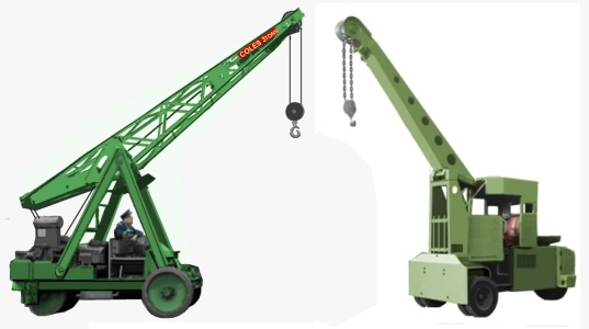
Modern diesel engined cranes, with hydraulic rams to lift and sometimes to extend the jib and an electric or hydraulic motor to wind in the hoisting cable, started to appear in the late 1950s. These use a compressor to provide the hydraulic pressure and because compressors heat up the fluid they use oil rather than water to avoid the risk of steam forming. The example shown below is traced from a photo taken in the 1950s showing such a crane being used to load coke into road lorries. Note there is limited articulation and little use of the hydraulics, the jib is raised and lowered by the two rams behind the cab, and the grab is operated by hydraulics, but the rest is all mechanical linkages. Note the double wheels at the front, single at the rear.
Fig ___ Early mobile hydraulic crane
The application of hydraulics to produce more complex articulated and extending jibs had to wait for general engineering to catch up and produce sufficiently accurate parts and effective seals but by the 1980s most rail mounted cranes were of this general type.
Note that by the mid 1930s cranes were by law clearly marked with their safe working load, usually in the form SWL 1 TON written in white on both sides of the jib (the law requiring the safe load to be established had been passed in 1844 but it was the 1880s before the tests produced meaningful results). The size of the lettering varied depending on the type of crane, small hand cranes where the operator was standing close to the jib might use lettering as small as two inches high but for large cranes with a cab the lettering was usually the full height of the jib side. In the 1920s and less commonly in the 1930s some cranes had something like 3 TONS written on the side but the safe working load was a legal requirement so the SWL abbreviation soon became standard.
Up until the 1960s for regular heavy loads the best option was the overhead gantry crane, some were fixed in position, others mounted on a bridge across two parallel raised rails (technically 'travelling gantry cranes'). Larger railway yards often had a gantry crane, some were fixed but most I believe were the travelling type (often called a Goiliath crane by railwaymen).
Kibri do a rather nice vintage gantry crane (B-7452), this has a fixed base and a covered gantry with railed walk ways and can span two tracks. Vollmer offer a modern tubular metal fixed gantry crane (7901), which would look well on any layout set after the 1960s, and as mentioned elsewhere they also offer the only really convincing ISO container handling crane (7905). The British firm Knightwing offer a neat cast white metal small fixed gantry crane well suited to industrial use.
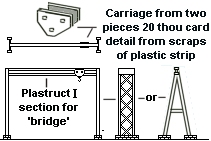
Two types which the modeller might attempt are the very small gantry or overhead conveyor and the very large travelling gantry crane suitable for a heavy engineering factory or larger railway goods yard. The sketch below shows the most basic form, a simple I section rail with a carriage running on the bottom web that might be used in an engineering works to lift heavy items on and off railway wagons (technically this is an 'overhead conveyor' rather than a crane). At a works the rail could extend into a building through a doorway (the doors being cut away to allow this) so items could be transferred to and from inside the building and the railway wagons. Note this requires two doors (usually sliding rather than hinged), one either side of the top rail!
Fig ___ Small industrial gantry crane
For N Gauge you can make a large travelling yard crane (sometimes called a Goliath crane) using Plastruct I section girders for the side rail beams and Heljan OO scale 'modern lighting masts' for the supports. You trim off the light from the top of the mast and cut a notch in the lower web of the 'I' beam so the mast can be glued in place. Add a smaller I beam from the Plastruct range to the top to represent the running rail (you could use Peco rail recovered from a length of the old-style flex track but that is a bit big). The 'bridge' can be made using two sides of 30 thou card, cut to a 'fish-belly' shape with detail added to the outer sides from 10x20 thou strip, small section Plastruct I girder would do for the top mounted rails and the carriage can be made up from plastic card, strip and tube (lengths of threaded bolt can be used for winding drums if these are exposed). One point is to ensure that the two supporting rails are a fixed distance apart!
One variant on this idea was the travelling crane which had the trolley suspended underneath the bridge, equipped with a jib that could be rotated. This allowed the jib to be poked out through a doorway to transfer to or from road vehicles parked outside beyoind the span of the bridge itself (that might be of interest on a model if the end of a building were sufficiently open to reveal it).