Although not technically a 'yard' refuge siding were an essential part of freight working in the days when freight trains running at twenty miles per hour shared the line with express passenger trains. The slow moving goods trains would be side-tracked onto passing loops or backed into long `refuge sidings' to allow the higher priority passenger trains to pass. There are a number of these loops and sidings still in use on the railways, on the line between Altrincham and Stockport there is one of each in the vicinity of the waste disposal depot and cement depot at Northenden. The loop was used for shunting the cement sidings which had only dead-end sidings. The refuge is used mainly for engineers trains when work is in progress in the area. On double track lines the refuge siding was accessed by a trailing point, so the train would reverse into the siding. Loops are more complicated as they require a secure lock on the facing point.
Exchange Sidings
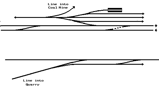
Exchange sidings, as the name suggests, were used to allow railway company trains to drop off and collect wagons associated with larger industries. Examples would include docks, coal mines and steel works. The railway company engine would collect and deliver wagons to the exchange sidings whilst the works shunting engine would operate between the sidings and the works.
Obviously at some point either the works engine or the railway company engine will have to run on the others lines. For safety reasons it was always the railway company engine that trespassed in this way, the exchange siding would be separate from the main line and access to the latter would typically be via a kick-back arrangement to avoid the possibility of a works engine running out onto the railway company line.
Because they were technically 'outside the railway fence' exchange sidings have not had the same amount of coverage as more mainstream railway goods facilities but examples can sometimes be found in the more detailed histories of specific lines. Exchange sidings offer real potential for a model layout, they were smaller than a marshaling yard (described below) but still offer some useful 'on layout' goods stock storage and on a continuous run they can be accessed from the fiddle yard, allowing a realistic directional flow of full and empty wagons. They are a feature well worth making a note of when studying prototype track plans.
Exchange Sidings
Marshalling Yards
Marshalling yards were functionally the junctions in the railway goods services. It was in the marshaling yard that a train arriving from one route would be broken up and the stock added to rakes being put together for the final destination. They were located at railway junctions and on the periphery of large industrial areas and smaller yards were provided where several branch lines converged onto a main line route.
Each of the railway companies operated their own marshaling yards and all of these were inherited by the nationalised system. As recently as 1963 there were some six hundred marshaling yards still in use, with capacities ranging from a few hundred wagons to a few thousand. Trainload or block load traffic and the air-braked Speedlink and Enterprise wagon load traffic services require relatively little marshaling and by 1982 there were only fifty nine marshaling yards in operation on the whole of the British Railways system.
As noted earlier the railways had to cater for a range of traffics, some of which were seasonal, others intermittent. They built their rolling stock to be as general-purpose as possible but a lot of goods stock spent a lot of the time lying idle, usually in the marshaling yards. Since the 1980's the shift to the intensive use of specialised stock has meant a reduction in the numbers lying in the yards awaiting their next job of work, but general purpose goods stock and a lot of the engineers stock can still be seen sitting on a siding for days on end.
In the days of steam engines it was common to have a turn table for visiting locomotives at a marshaling yard and there was usually some form of engine shed for the pilot shunting loco (normally a tank engine). One small point is that shunting engines normally operated with the boiler or engine housing pointing 'into' the yard to give the driver an unobstructed view when he was approaching the main running lines.
A marshaling yard has two sets of sidings, the arriving rakes of wagons are deposited on the reception sidings which were commonly formed by a series of loops to ease shunting and the outgoing rakes are formed up in a series of 'sorting sidings'. Quite often there was one road in the reception sidings set aside for departing trains, the rake would be deposited by the pilot engine, which would also attach the brake van to the appropriate end, and the main line engine would collect the train from the loop.
You need only have a couple of reception sidings although busy yards would have quite a few and there would be rather more sorting sidings, generally one for each destination being served by the yard. There was generally a separate siding provided for damaged or suspect stock, or wagons with loads that had shifted and become unsafe (this was known as the cripple siding) and there would also be a siding or two to store brake vans. The sorting sidings were often all dead-ends, the made-up train would be pulled back into the reception sidings (where a brake van would be attached) ready for despatch.
The tracks would generally be separated by slightly more than the standard six foot spacing used on running lines to allow staff access for coupling and uncoupling the wagons. Marshalling yard staff had to see to couple and uncouple the stock and also had to be able to read the `waybill' so there would be some yard lighting, either single gas or electric lights on tall posts or batteries of electric lights on pylons. No goods handling facilities would be provided at a marshaling yard although a mobile crane with its match truck or runner wagon might be available to assist when dealing with a shifted heavy load.
As you probably require something like five foot of siding space for a decent length of goods train (roughly thirty wagons) the normal arrangement of a series of reception sidings feeding into the sorting sidings means you would need something like thirteen or fourteen foot (400-450cm) for a small marshaling yard in N gauge. This can be reduced somewhat by having the reception sidings parallel with the sorting sidings and using a head-shunt (which can curve easily alongside the main line) for the process of sorting.
Fig ___ Typical marshaling yard track plan

Fortunately not all marshaling yards were this big, at the junction stations on country branch lines it was not uncommon to have a few sidings accessed from the station loop for storing and marshaling local goods trains. These sites did not boast the full facilities of a main line marshaling yard and represent a practical option for modelling. As an example the line between Manchester and Chester via Altrincham had a simple set of sidings just outside Altrincham to serve the Cheshire Midland Railway goods trains, close by was the link to Skelton Junction, the hub of the Cheshire Lines Committee system, which linked the LNWR Manchester to Crew main line with CLC lines to Warrington and Liverpool as well as the Midland Manchester-Chester line (see Fig ___).
On a double tracked line there would often be an `up' yard and a `down' yard. These were usually placed to either side of the main line and stock would have to be taken across the main line during sorting. To avoid any possibility of a shunting train finding itself on the main line, or an express finding itself wandering into the yards it was usual to use diamond crossings for this link. Generally access to the yards would also entail either a loop line or reversing clear of the main line, again to minimise the possibility of trains wandering where they shouldn't.
'Catch points' would be placed near the junction with the main line. Peco provide both left and right hand working catch points remember you want the runaway to turn away from the main line when it comes off the tracks. Alternatively these points can be made up in dummy form using short lengths of rail, which has the advantage of enabling them to be fitted onto a curve.
The sorting of wagons into rakes at the marshaling yards was mainly accomplished using the pilot locomotives to haul and push rakes about but some yards had been built on inclined gradients, where gravity could be used to roll wagons down into the sidings. Known as 'gravity yards' these were a lot more economical, but they were dangerous places to work as a man had to run alongside the wagon and apply the hand brake to control it. See also Railway Company Goods Facilities - Introduction & Shunting Methods.
Gravity yards found favour with the railways as they did not require a shunting engine to work them. At the Manchester end of the LNER trans-pennine Woodhead route a large marshaling yard was established at Mottram in 1935. This was built on a natural gradient of 1:85 and was gravity worked. This yard accepted trains coming into the area, splitting them up for their various destinations on the Lancashire side of the Pennines. There were eight reception sidings, each long enough to hold eighty wagons and twenty sorting sidings each capable of holding sixty five wagons. Mottram yard remained in use until the closure of the Woodhead route in the 1980's.
A logical development was the `hump yard' in which a rake of wagons is pushed up one side of a man-made hump, uncoupled one by one (or in short rakes called 'cuts') and allowed to roll down the far side into a fan of sidings. One of the first hump yards, the LNER marshaling yard at Wath, serving collieries in the Barnsley area, was built in 1907. The approach to the hump might be as steep as 1:30 whilst the tracks leading down into the sidings was more gentle, perhaps 1:60 at the hump end with a gentle transition to the horizontal in the sidings themselves. The sorting sidings at hump yards were formed from a series of loops (otherwise the completed trains would have to be dragged back over the hump) and the yard itself was usually on a loop separate from the main line.
Operating a hump yard involved three men at the crest of the hump, one tally man keeping track of the wagons, a shunter with a pole who uncoupled the wagons at the top of the hump and a man who applied the hand brake so the wagon would not roll too quickly down the sidings. The points were controlled from a central signal box, usually called the control tower, but this system still required men to run alongside the wagons and apply the hand brakes in the sidings with the consequent risk of injury. One way to reduce the risk to staff was to supply chocks that could be placed on the track to stop a wagon but these sometimes derailed the wagons. In the 1920's `automatic retarders' were developed, these were hydraulic chocks that slowed the wagons down to minimise the shock when they hit the already parked stock. The first British yard to use retarders (of the German Frohlich design) was built in 1929 by the LNER at Whitemoor on the old Great Eastern line.
The upper sketch in Fig ___ shows a suggestion for a model railway hump yard, the arrival and sorting sidings each need to be about five feet long. The overall length required would therefore be in the region of sixteen feet in N, so this would only be practical in a very large room or a garage. The hump yard and its track mounted retarders formed an important element in the 'Modernisation Plan' of the 1950's and development continued right up into the 1970's. The lower sketch in Fig __ is a loose interpretation of the layout at the Edinburgh Millerhill yard built in the diesel era. The sketch is based on notes made from an Edinburgh bus company map in the 1970's and is not terribly accurate. The real life yard had a lot more loops in both sets of sidings but the basic outline is about right.
Fig ___ Hump-shunting marshaling yards track plans

The automated hump yard was in the final phase of development when Beeching's report pushed the railways toward withdrawal from the single wagon load and sundries traffic business for which the yards had been built. Most of the larger hump yards in England closed in the mid 1980's, by which time the retarders were starting to show signs of their age. This also brought the end of the three diesel shunters of Class 13, consisting of a standard 08 loco with a second similar but cab-less loco permanently coupled to it.
Some stock, used for the carriage of fragile items, or built using fragile materials was marked `Not to be hump shunted', milk tank wagons with their glass lined tanks were one example. When such a vehicle turned up at a hump yard a loco had to couple to the wagon and take it through the system. There was also a problem with the Mansell wooden centred wheels used on some non-passenger coaching stock such as horse boxes. These wheels had studs to secure the tyre to the wooden hub which would be chiselled off by the automatic 'retarders' used in 'hump' shunting yards, so vehicles with Mansell wheels had to be braked by hand as they ran down the track.
The last operational hump yard was Scunthorpe West Yard which closed in 1990 but I believe a hump yard operated by locomotives in South Wales remained in use until the mid 1990's when marshaling was concentrated at a flat yard near Cardiff. Shunting on the modern British railway system is entirely handled by locomotives. Hump yards are still used abroad, notably in America where there are several truly vast hump type marshaling yards serving the major junctions.