Prototype Goods Yards and wharfs
Many modellers prefer to at least base
their yards on real life prototypes and many of these contained interesting or
attractive features such as the single slip giving access to the cattle dock
and coal sidings at Hale.
Fig___ Hale Station
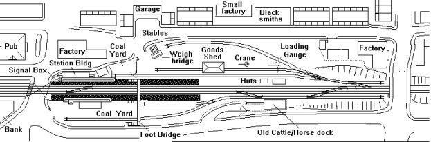
Hale station was on the southern fringe of the Manchester
suburbs, serving a number of local shops, some small industries and an
extensive agricultural hinterland. As a result this small station had a fairly
comprehensive set of features allowing most kinds of traffic to be handled.
I happen to have lived nearby at various times over the years and there is a separate appendix detailing the history of the station with details of the traffic flows.
Hale is covered from a signalling point of view in the section on signalling
and that section also contains a track plan for a busy single track country
station with a well appointed goods yard.
The
single track branch line has been a popular modelling subject, usually on the
rather dubious basis that the stations require less room than those on a main
line. In fact a small town station goods yard would probably be smaller than a
country station yard as land was more expensive in the town than in the
country. Again it is worth pointing out that even simple stations such as these
are not small in modelling terms.
Modelling Hale close to scale requires about
nine feet by eighteen inches (270cm x 45cm). It is possible to design a layout
incorporating all the main features of a goods yard in a much smaller space.
The three single-track layouts shown below
would require about six feet (2m) of baseboard if modelled to anything like
scale size.
Fig___ Selection of
prototype goods yard layouts
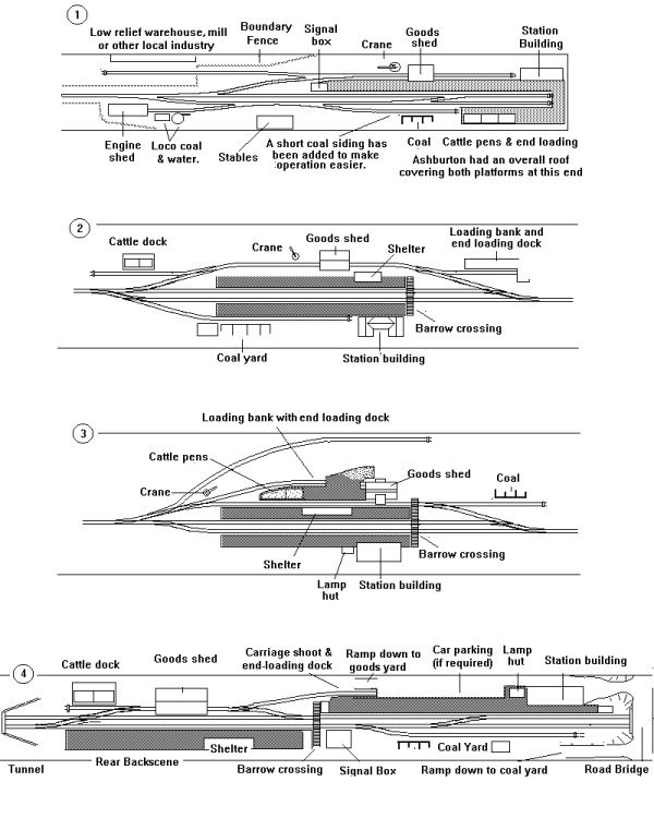
Fig ___ (1) is based on Ashburton, a popular subject for 'OO' scale modellers
although limited in operational interest. The layout as shown, with the
additional siding for the coal merchant, could be built on a baseboard four
feet long by ten inches wide. The model could be built using kits for the major
structures; Langley Masterbuild low relief warehouse, Ratio goods shed, cattle
dock and station building, SD Mouldings small signal box etc.). As shown in the
drawing a road over bridge at the left hand end could be used to hide raised
hinges and a second four foot board could then be added containing a simple
fiddle-yard. When not in use the two boards fold up to form a box four feet
long, ten inches wide and about five inches deep.
Fig ___ (2) shows a single track through station, very
loosely based on Cadeleigh on the Exe Valley line of the GWR. The layout has
been modified with the addition of end-loading facilities on a new siding to
the right and another new siding for a local coal merchant. The layout requires
slightly greater depth and assuming it forms part of an oval with twelve inch
radius curves at either end would require a minimum of about six foot of
baseboard length. This sketch assumes you will use the Ratio stone-built kits
for the main station building, the goods shed and the cattle dock. The smaller
platform shelter could come from any number of sources but the end loading dock
would require scratch building (perhaps with Peco platform edging). Note the
use of 'catch points' on the goods loop and coal siding.
Fig ___ (3) is based a friends OO layout which I believe was
based on a real station on the GWR but he could not confirm the location. The
Peco goods shed kit is suggested in the sketch but the platform and cattle pens
would need scratch building. The siding curving away to the top of the drawing
was a common feature of many yards, often used by the coal merchant. The
additional depth this siding requires is a possible drawback on 'shelf' type
layouts but it can be accommodated on portable single-piece oval layouts by
placing the yard toward the inside of the baseboard.
Fig___ (4) shows an alternative arrangement featuring
staggered platforms on a double-track line. This was not uncommon arrangement
as railways by their very nature tend to be long and thin rather than short and
fat. The track plan shown is not directly based on a single prototype but
includes standard features from several stations. In modelling terms the
platforms need to be an absolute minimum of four coaches long to provide enough
room for the goods loop. For an N gauge layout such a station therefore needs
to be a minimum of four feet six inches long overall but could be as little as
seven inches wide. The layout as shown should just fit on a baseboard five foot
six inches long by eight inches wide and could be used as an 'upper level' loop
line covering a set of eight storage loops. Note the use of a single slip at
the left hand end, this avoids having a facing point at the entrance to the
goods yard. In practice facing points were sometimes seen on such a goods loop
however I would still advise adding a second trailing crossover to make
shunting easier. The second crossover can be somewhere about the middle of the
left hand platform to save a few inches in length.
The through station layouts shown in Fig ___ all feature a
loop line through the goods yard, this was common practice but by no means
universal. Although the goods sheds shown are about the middle of the goods
yard loop it was not uncommon to see the shed sitting right on the end of a
dead-end siding. At Hale station the goods shed was half way along the siding
but the lack of any goods loop meant the main line has to have a loop for
shunting. At Hale the loop is formed from one trailing crossover and a single
slip and point (see above). It was equally common to have two sets of trailing
crossovers.
The railway was the principal
delivery system throughout the country and small industries often rented land
adjacent to or in a corner of the goods yard. Some of the larger firms with
regular traffic would have a private siding run into their premises. This would
be gated where it joined the goods yard or main line.
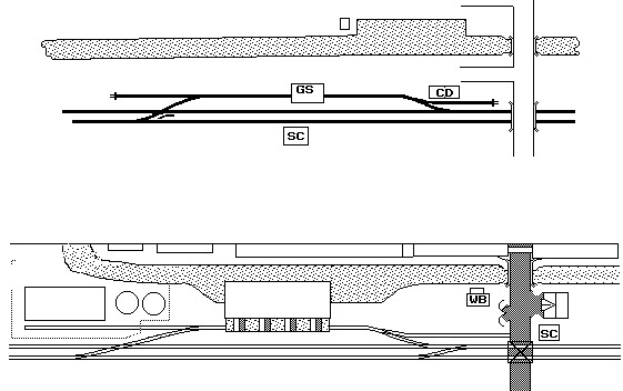
Goods yards were not only found at passenger stations, as an
example there was a small self contained goods yard at Burbage Wharf on the
Kennet & Avon Canal, served by the Great Western Railway. This is about the
simplest goods facility possible, the original layout was a single track main
line with a single loop passing through the goods shed and with two short
sidings at either end of the loop. The line was subsequently doubled giving a
track plan as shown in Fig ___ (1), note that using the run-round loop involves
passing over the slip onto the lower line then reversing back across the slip.
The canal traffic was mainly handled at the wharf on the opposite bank, the
goods being carried across the bridge to the railway yard, but some barges tied
up on the railway side of the canal. Further details on the prototype for this
goods station, including a photograph showing the end of the goods shed and the
cattle pens, will be found in the book 'An Historical Survey of Great Western
Stations' detailed in the bibliography.
The
lower sketch Fig___ (2) shows a modified layout as a suggestion for a model,
note the additional trailing cross-over to the right which simplifies shunting.
The suggested arrangement moves the canal wharf to the railway side of the cut,
the simple goods shed is replaced by a large canal warehouse with an awning and
boxed-in hoists over the railway track. The over-bridge across the railway is
dispensed with, replaced by a level crossing and the opposite bank is now
occupied by the tow path and a series of large industrial buildings in low
relief as this requires much less room. The head-shunt to the left is extended
into a works of some kind to disguise the canal passing into the back-scene and
a little thought here could provide some interesting traffic on the line. An
enamelling works for baths and the like would see open wagons of coal and
baths, with vans for smaller goods and the powders used in the enamelling
process. The alternative shown is a turpentine distillation works taking in
resins from pine trees and producing a range of oily and solid materials
including rosin (a solid yellowish material used for coating violin strings
amongst other things). This option would offer the chance to run non-oil tank
wagons of various kinds, open wagons loaded with wooden barrels and steel drums
and a selection of van traffic. To further disguise the join with the back
scene you might add a foot bridge over the canal, an etched brass lattice type
would be appropriate. Alternatively the low relief buildings on the left could
form part of the works, linked by pipes over the canal. Small pipes would
probably require the support of a lattice girder frame but pipes more than a
foot or so in diameter could be supported on a simple brick pier on each side.
Remember you need to leave the towpath on the canal bank clear.
Fig ___ Sketch of Burbage Wharf
The
prototype for the above layout modelled to scale in N would require some six
feet (1.8 m) of baseboard length and at its widest point (the over-bridges) it
would be about twenty inches (50 cm) wide. The prototype canal would be some
two and a half inches (63 mm) wide in N, making this a narrow canal reduces
this to one and a quarter inches (32mm) plus half an inch (13mm) for the tow
path. In the above example you do not need to allow sufficient length of loop
for running round a full length goods train. Providing the wagons to be
deposited at the wharf are at the locomotive end of the rake the remainder of
the train can be left further up the track whilst the wharf is shunted. On a
model railway you will commonly see a train about every minute and a half, in
real life services on such a branch would be at their busiest only about once
an hour, allowing plenty of time for this kind of shunting.
Where there was a local demand a separate isolated goods only
station might be built on a main or branch line apparently in open country.
These were not common but they did exist, the facilities being determined by
the nature of the local demand and the available land at the location.
Fig ___ Goods station or wharf
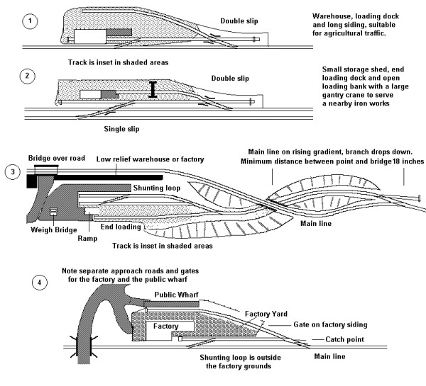
The goods station shown in Fig___ (1) offers basic facilities
for goods which might be manhandled including a goods shed and a loading bank.
Fig___(2) shows the arrangement for a similar station on a double track line,
note the single slip at the left to avoid facing points on the running lines. A
separate trailing crossover on the main line is not required as the loop in the
goods yard can be used.
In remote locations
with a steady supply of goods to be moved the railway companies sometimes opted
for a goods-only branch line feeding a small goods-only station. Fig___ (3)
shows such a branch line feeding a lower level. These remote goods stations
were, usually called a 'wharf' or 'public wharf' on the original plans. The
North Staffordshire Railway had quite a few of these goods loading points. In
some cases when the NSR laid a siding into an engineering works they stipulated
that the siding should also serve a public loading bank or wharf. Fig___(4)
shows the most basic arrangement, this is very loosely based on the original
track plan for a siding into a steam locomotive works in Staffordshire.
The smaller town goods yards usually had a larger version of
the standard goods shed. Again this was often separate from the passenger
station, usually being located along the main line rather than alongside the
station platforms.
A good example, showing
just how long this arrangement can get, is Altrincham on the Manchester-Chester
line. Modelled to scale in N Gauge with the original track plan this would
require about thirty feet of baseboard so in the drawings which follow I have
modified the layout to reduce its length. Altrincham was the terminus of the
Altrincham-Manchester 1500v DC electric passenger services and has quite a
large passenger station with two platforms with overhead electric wires for the
EMU services and two more for steam or diesel trains continuing on toward
Chester. The 1500v DC system was changed to 25Kv for a time but Altrincham now
serves as the southern terminus for the new Manchester 'tram' system. The
non-electrified platforms remain in use for BR diesel multiple unit passenger
services and the line to Chester still carries freight traffic. The
Altrincham-Manchester line was connected by the junction shown in the lower
right to the line running between Warrington and Skelton Junction, the hub of
the Cheshire Lines Committee system. Skelton Junction is located just outside
Stockport, itself a major junction station on the Manchester-Crew route which
feed onto the West Coast Main Line from Glasgow to London main line. The line
to Stockport still carries an hourly DMU service from Chester and carries
freight for the chemical plants of Cheshire. This line also serves the
Manchester containerised waste disposal depot and a Blue Circle cement depot.
Traffic for both these establishments passes through Altrincham on occasion.
The line to Chester carried a considerable
freight traffic, most of which travelled via Skelton Junction. The
Altrincham-Stockport line remains in use (with a cement terminal and the
Northenden refuse disposal terminal providing additional freight workings), the
freight only line continuing out to Warrington was closed down in the 1980's
and the once vital Skelton Junction has been considerably simplified and has
lost its once busy marshalling yard sidings. At the Chester end of Altrincham
station there was a set of sidings, these were in fact the remains of the
original terminus of the line. These were used for stabling the Oilerkon 1500v
DC Electric Multiple Units but I remember seeing goods vans and opens stored
there in the early 1980's. This makes an interesting feature for a corner, but
the space could equally well be used for a combined carriage shed and loco
depot for local suburban commuter services. The turn-table shown on the drawing
was quite small and I believe it was removed at about the turn of the century.
This entire area is now a car park.
Altrincham goods yard was located beyond a level crossing at the Manchester end
of the station, two long loops were provided at this point as the Midland
Railway had a set of sidings located just beyond the goods yard. Note the
'catch points on the loops and sidings.
The
drawing below is based on Altrincham, it is not an exact copy of the original
track plan but has been adapted to make it more suitable for modelling. The
coal yard on the prototype was a series of sidings running from the station
behind the signal box fed from a series of loop lines behind the platform. I
have relocated the gas works, in fact this was quite some distance from the
station connected by a lengthy street 'tramway' leading out of the coal yard
via a small loop as shown. To save some space I have not included Navigation
Road station, which was between the level crossings and the junction. I have
also missed out a short length of track and two over-bridges on the line to the
old terminus (originally called Bowdon Station) to allow this to fit into the
space left by the rather tight model railway curves.
Fig ___ Suburban station goods facilities
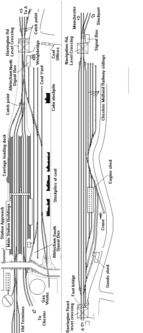
The layout as shown in the drawing would still
be over twenty feet long in N. That is about eleven foot for the passenger end,
assuming two-foot radius curves for the Chester line, with a similar length for
the goods yard and junction. That allows for a maximum of six coaches in a
passenger train and the loops between the two level crossings would hold a
fifty-wagon goods train with it's loco and brake van to allow a passenger train
to pass. In a more modern context the loops would be useful for stabling
permanent way wagons waiting for a quiet time on the line to do their work.
Note that the area for actually handling goods in the goods yard is not really
very large. The facilities consist of a single loop with a two-story goods shed
(the line passing by outside, not passing through the building) and a small
area in the open.
In larger towns up to the
1960's there would be a goods yard associated with each of the old railway
company main stations. Town goods yards were often separate from the passenger
station and may be marked on maps as a 'goods station'. At the larger goods
yards there might be separate lines for arriving and departing trains to be
sorted as well as the sidings on which the wagons were loaded and unloaded.
There would also usually be storage sidings associated with such a large
station, for stock awaiting attention or special vehicles kept on hand such as
carriage trucks and horse boxes. These sidings might well be combined with some
carriage sidings on the approach line.
^
Go to top of page
International Good Guys ~ Making the world a
better place since 1971 ~ Site maintained by

All material Copyright © Mike
Smith 2003 unless otherwise credited