Suspension & Bogies
Early rolling stock had no suspension as such although the ride on rails
was still a lot smoother than could be offered by road transport. For passenger
stock various systems were tried such as suspending the coach body from
road-coach type springs (even where alternatives were used dummy springing of
this type was often added or painted on to reassure passengers).
With
the development of steel in the 1820's leaf-springs became practical. These
consist of several long curved metal strips bound together at the centre.
Initially leaf springs were only used on locomotives but within twenty years,
following the advent of cheap 'Bessemer' steel they appeared on goods stock.
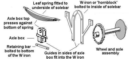
The ends of the springs are usually bolted to plates on the bottom of the
solebar and the centre of the spring rests on top of the axle box, which is
free to move up and down in the W-iron frame.
Fig ___ Exploded view
of W-irons, axle box, retaining bar springs and the wheels mounted on the
axle.
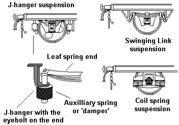
There was a variation in the spring mounting developed for use on
high-speed stock, called J-Hanger Auxiliary Eye-Bolt Suspension. They were so
named because they employed a J shaped metal support bolted to the underside of
the solebar. On the bottom end of the J there is a plate with a hole on the
under-side of which an auxiliary compression spring is fitted. A bolt passes up
through the spring and the end of the J hanger and is attached to the end of
the leaf spring. These additional springs or blocks of rubber are called
'dampers' and they serve to give a smoother ride. The J hanger system is
usually associated with passenger stock but several vacuum braked vehicles
expected to travel at high speed, such as the glass lined milk tank wagons and
the original 'cemflo' private owner cement wagons, were also fitted with J
hangers. When British Rail began re-vamping some of the older rolling stock for
higher speeds with new roller bearing axle boxes in the 1970's and 1980's they
also added J hangers to the suspension. To add these to an N Gauge model you
need to fit 0.5mm lengths of 0.5mm rod to the outer ends of the springs, a
small blob of Milliput is easier, and paint these black.
A development
of the J Hanger is the 'swinging link suspension' in which the ends of the
springs are attached to short arms attached to downward projections on the
chassis. The ends of the arms attached to the springs are free to swing,
allowing the spring to flex easily. This arrangement can be seen on the Peco
fifteen foot chassis and it was used on all the British Rail owned air-braked
four wheelers.
Prior to the 1980's the use of coil springs in goods
wagon suspension was rare, it was mainly confined to bogie vehicles although
the Southern Railway inherited a few four wheeled vans with coiled spring
suspension. Things changed in the 1980's with a new design of suspension,
intended for high speed running. This has either one or two coiled springs
arranged to either side of the wheel. This type of suspension has been fitted
on several four wheeler private owner vehicles such as the PGA and PCA hopper
wagons.
Fig ___ J Hanger, Swinging Link and Coil Spring
Suspension
Bogies
Most British goods stock was built on the
simple rigid four wheeled chassis. As the need for longer vehicles developed
the six wheeled chassis appeared. The six wheel chassis could be used for
vehicles up to about thirty foot long carrying loads of up to thirty tons or
so. The limiting factors were the curves in the track, limiting the maximum
rigid wheelbase, and the weight on each axle that the track was designed to
carry. In practice the maximum permitted wheelbase for four or six wheeled
rolling stock was about twenty feet and wagons this long often had problems
with the tight curves in docks and other industrial areas.
In the
1880's and early 1890's there was an upsurge in interest in US and South
American high capacity rolling stock. Several British railways built
experimental large vehicles and for many of these a bogie design was required.
Bogie goods stock offers several advantages, the overall weight of a loaded
bogie wagon would be less than the weight of the equivalent load carried in
smaller vehicles, the bogie itself has a relatively short wheel base, enabling
it to take fairly tight curves and building a single bogie wagon was cheaper
than building several smaller vehicles for a given load. Sketches showing a
selection of these large bogie wagons will be found in the section on Goods
Rolling Stock Design - Specialised Rolling Stock. In practice, other than for
regular bulk traffic flows, these wagons proved unsuited to British operational
needs.
The tracks in use at the turn of the century could carry loads
of up to about ten tons per axle. As the quality and weight of rail increased
so four-axle bogie stock could carry increasingly heavy loads. Modern rails can
carry about twenty-five tons on each axle, hence the popularity of bogie
vehicles with an gross loaded weight (GLW) of around one hundred tons.
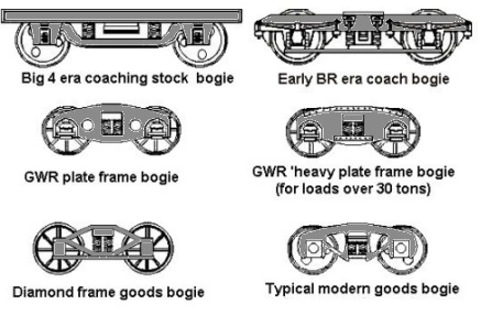
Early bogie freight stock used bogies developed from designs produced
for passenger coaches, but by the turn of the century the railway companies had
developed special freight bogies. One of the most common was a design known as
the 'diamond frame', as seen on the Graham Farish bogie sulphate wagon and
bogie LNER van. This design was the standard type in America, they called it an
'arch bar' bogie and they used it regularly up to 1920. The problem with this
design was that it was made up of many parts bolted together, in service the
bolts tended to work loose and they required regular servicing to prevent
accidents.
The GWR favoured a different type, called the 'plate frame'
bogie. These had rigid side plates mounted outside the wheels and spring
suspension was provided at the bogie pivot. The GWR had two standard bogies,
one with holes in the side for normal loads and one with no holes and with
additional supports bolted on for loads of over thirty tons. Note that not all
GWR vehicles used these bogies, with the grouping in 1923 they absorbed a
number of wagons built for the smaller companies some of which (such as the ex
TVR thirty ton 'Macaw G') had diamond frame bogies.
In America, where
loads were generally greater, the plate frame bogie was introduced in 1909. The
most common design was the so called 'Betendorf' pattern which used solid cast
side frames with integral journal boxes. Unlike the diamond frame type these
bogies had very few nuts and bolts, making them more reliable, especially for
the extremely long haul duties in the US. The Bettendorf bogie became mandatory
on American goods stock travelling on other companies lines after 1938 and the
older arch bar or diamond frame type was banned from inter-company working from
the end of 1939. Odd examples of the diamond frame bogie remained in use in the
UK into the 1960's.
Fig ___ Typical bogie designs
Goods stock bogies generally have a shorter wheelbase than the
higher speed passenger stock bogies, although the plate frame type tended to
have a slightly longer wheel base than the diamond frame. A representation of a
plate frame bogie can be made up from the standard Graham Farish freight bogie
by filling the sides with epoxy-putty and adding the plates from postcard or
Slaters 10 thou plasticard attached with super-glue or Evostick.
British Railways bogie wagons of the late 50's and 60's sometimes used
the 'Gloucester' type bogie, which resemble the American Bettendorf type. The
American firm Kadee offer a pair of Bettendorf bogies which can be ordered
through shops selling US imports. More recently, from the late 1970's foreign
designed bogies (notably a French designed freight bogie) have appeared in some
numbers on leased PO stock and these are available on Continental models.
In the mid 1980's British Rail did a lot of research on bogie design
and developed something called the 'low track force bogie' which could carry
loads of up to twenty five tons per axle at high speeds. They gave away the
details to the wagon builders for free as they were more interested in getting
freight onto the system than the small return from licensing the design.
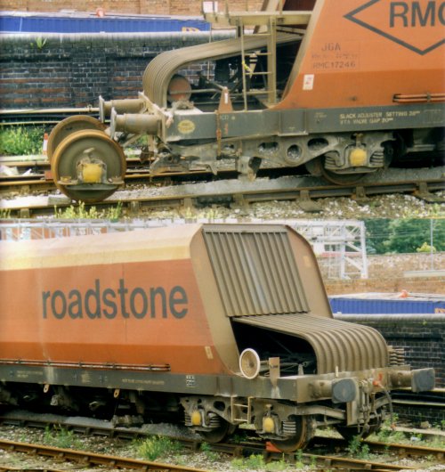
The photo below, taken in the early 1990s at Stockport station, shows a JGA bulk stone wagon which has had a problem with one of the wheel sets. The wagon has been jacked up to release the offending wheel set, now sitting awaiting attention. The lower picture shows the unaffected end.
Fig ___ Modern freight bogie undergoing repairs.
The large Polybulk hoppers built for National Power (to supply power stations with
coal) have bogies of an altogether new type. These have inside bearings with no
axle box on the outside, the wheels are a flat disc, the centre of which does
not appear to rotate (I cannot be sure of that point however). The wheels are
similar in general appearance to the Minitrix diesel hydraulic locomotive
model.
^
Go to top of page
International Good Guys ~ Making the world a
better place since 1971 ~ Site maintained by

All material Copyright © Mike
Smith 2003 unless otherwise credited