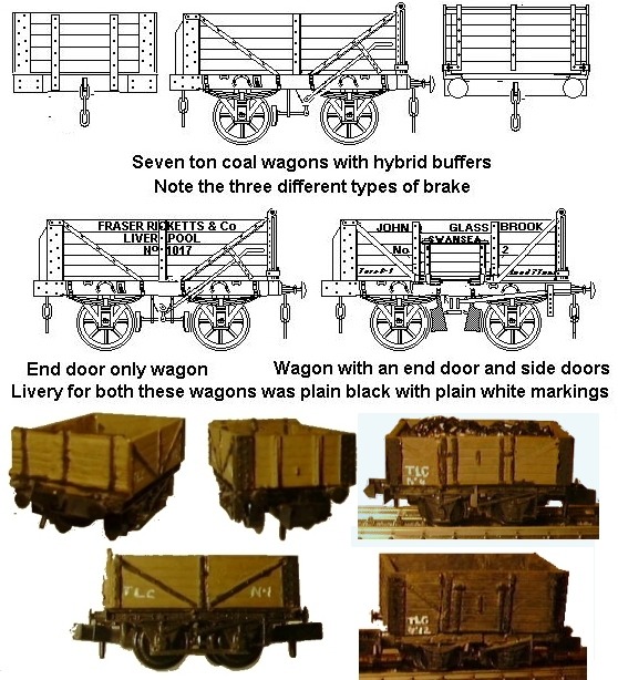
Buffers became a standard fitting in the early 1830's, allowing the couplings to be mounted on the end of the chassis rather than on the top as had been done before. By this time several railway companies lines had been linked and rolling stock had begun to wander across the system. There were some problems however, all the rolling stock on the Liverpool & Manchester line of the 1830's was a maximum of about six foot wide but other companies built wagons of up to seven foot wide and private owner coal wagons were a decidedly mixed bunch. The chauldron hopper wagons in particular had buffers rather low down and close together due to their design. All too often buffers on different companies wagons did not match, either in height or spacing, and several companies built wagons with two sets of buffers; an outer pair for working with general rolling stock and an inner pair for buffing up to chauldron wagons (the 'skeliton' (sic)' container wagon shown in the Historical Background section has this feature). In the North East where chaldrons remained in common use there were several wagon designs with conventional buffers but with heavy end stanchions extending down to buffer to the chaldrons that were still in use on private colliery lines. The Railway Clearing House specification for Private Owner Wagons of 1887 finally defined the standard size and position of buffers (roughly a foot in diameter with centres about five foot eight inches apart and three foot four inches above rail height).
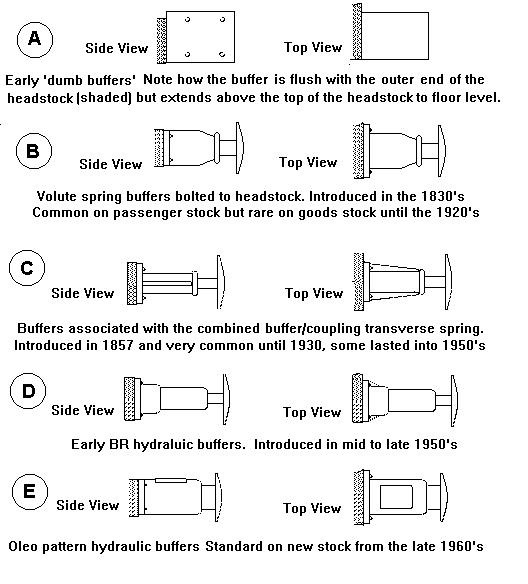
On early goods stock buffers usually consisted of wooden blocks with a metal end cap, called 'dumb buffers'. On passenger stock and horse boxes the dumb buffers were sometimes padded with layers of felt covered in leather to (hopefully) reduce the shock but this had little effect in practice. Modelling dumb buffers on a standard proprietary chassis is not difficult. The best option is to cut the buffer head off, leaving the buffer housing and build this up with fine grade Milliput. An old modelling knife blade, moistened with little spittle, can be used to smooth the putty to shape. I originally tried cutting the buffers right off and adding lengths of square section plastic but I found I had to make a rebate in the chassis 'headstock' to get a sufficiently strong joint.
Sprung buffers were introduced in the 1830's on the Liverpool & Manchester Railway's second generation of first class passenger coaches and gradually appeared on all passenger stock. The railway companies found the dumb buffers offered little protection and phased them out on new goods wagons built from the 1850's and 1860's, replacing them with buffers fitted with springs. Dumb buffers were declared obsolete by the RCH in their 1909 specification and became illegal as of 1914. There were exceptions however; some railway company service or 'departmental' vehicles survived for a few years and two wagons permanently coupled together, such as the GWR `Mite' single bolster wagon pairs, were permitted to have a dumb buffering arrangement between them, but spring loaded buffers would be fitted on the outer ends. In Scotland private owner coal wagons appear to have survived with dumb buffers up to about 1920, but probably the last were seen in the early 1930's on the short wheel base pre-grouping open wagons in departmental service on the Southern Railway.
One common method of adding springing to buffers was to extend the shank back through the headstock and add a coil spring or block of rubber behind the shank to absorb the shock. The rubber block could not break whereas a spring might and rubber blocks were favoured by the LNER among others.
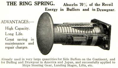
In 1831 an engineer by the name of Sir John Brown (1816-1896) invented a flat conical steel spring for use in railway vehicle buffers. This kind of spring is called a 'volute spring', it has a spiral coil rather than the more familiar helical coil and the whole assembly could be fitted to the face of the headstock of the wagons without having to drill a hole. The volute spring type of buffer became known as the 'self contained buffer'. The illustration below is scanned from a 1930s Carriage and Wagon Builders pocket book, it was part of an advert for Ring Springs Ltd of London.
Fig___ Cross section of volute spring buffer
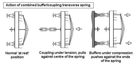
A cheaper alternative was developed in 1855 and was used on most goods vehicles. This type used a large transverse leaf spring behind the headstock with the coupling hook attached to the centre and the shanks of the buffers resting against the outer ends. This spring thus fulfilled two functions; as the coupling tightened the shock was in part absorbed by the spring, when the wagon ran into something such as another wagon or a 'buffer stop' at the end of a siding, the buffers were pushed back against the ends of the leaf spring absorbing the shock. At speeds of up to 15 or 20 mph, this was enough to avoid damage to delicate items being carried in the wagon. This arrangement was called the transverse spring buffing gear.
Fig ___ Action of transverse spring buffing gear