Couplings & Hoses
In the very early days the coupling chains were often long and Y
shaped with two ends attached to the top of the solebars of the
wagon. The trailing end of the Y carried a hook which could be
attached to the coupling of the next wagon. With the Y shaped chain
attached in this way the 'pull' was applied to the solebars rather
than trying to detach the headstock. In some cases, judging from
contemporary illustrations, a hook was fitted to the top of the
headstock onto which the trailing end of the chain was slipped. An example of this coupling can be seen on the sketch of the chauldron hopper wagon shown in the section on Goods Rolling Stock Design - Introduction
The
introduction and standardisation of buffers allowed the mounting to
be moved to the front face of the headstock and by the mid 1840's two
standard couplings were used in the UK; the 'five link' and 'three
link'. These consisted of five or three links of heavy chain as shown
in the sketch below. One end of the chain was mounted in a hole ('a')
in a large hook. The hole in the hook was in the shape of an inverted
'keyhole' ('b') and there was a slightly flattened section on the
chain ('c') that allowed a broken chain to be replaced easily. The
hook was attached to the end of the wagon chassis and the chain hung
down from this. The end of the chain from one wagon was lifted up and
slipped onto the hook of the next to couple the wagons together. Five
link couplings were never very common, the Railway Clearing House
specification of 1887 favoured the three-link and in 1905 the RCH
ruled that the five link couplings still in use were to be replaced
by three link couplings by 1914.
Fig ___ Typical three-link coupling 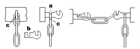
Using the standard British three-link couplings meant the
wagons had a degree of slack, perhaps a foot or so between the
buffers. This was called 'loose coupling' and offered the advantage
that a loco with a heavy load which had stopped could 'set back' the
train, that is push all the wagons together, then pull away again.
When starting like this the loco only had to overcome the inertia of
a single wagon at a time but care had to be taken as if the loco
gathered speed whilst starting off the jerk on the couplings would
become progressively stronger and it was perfectly possible to break
a coupling in this way. When pushed together the wagons took up less
room on a siding and the crash of loose coupled wagons being shunted
to save siding space was characteristic of British railway yards up
to the late 1970's.
Loose coupling, had its drawbacks, for
one thing it meant the wagons or vans tended to bang into each other
as the train travelled along. It was found that brake connecting
pipes (discussed in the following pages) became disengaged in transit
due to the jerky movement of the wagons. To get round this problem
two variations on the 'three link' were developed, both reduced the
amount of slack and so were called 'close coupling'. The most
sophisticated was the screw-link coupling patented by Henry Booth in
1837. On the screw link coupling the centre link of a three link
chain was replaced by a threaded bar with a lever on it. The stock
was shunted together, so the buffers were just touching and the
shunter would hook the free end loop over the hook on the next wagon
as normal. He then turned the handle on the threaded bar, pulling the
outer links together so that in transit the buffers remained
touching. This took time however and was only generally applied to
passenger stock. A twelve coach train only had twelve couplings to
adjust but a long goods train had perhaps a hundred, and these had to
be operated whenever a wagon was dropped off or collected en route.
Screw link couplings were standard fittings on 'non passenger
coaching stock', fish vans, banana vans, horse boxes, milk churn vans
and milk tank wagons which were routinely coupled to passenger
coaches. Up to about 1926 these vehicles had to have two extra chains, with large hooks on the ends, attached to the head stock to either side of the coupling. These were called 'security chains' and were only used when the vehicle was attached to a passenger coach.
Also where vacuum brakes (discussed below) were
fitted the screw type coupling was usually specified to avoid the
pipes being disconnected as the wagon jerked in transit, the LNER
used screw couplings as standard on all its vacuum brake fitted
wagons and vans. Other companies goods vehicles, mainly longer wheel
base vans likely to get marshalled into a passenger train, were also
sometimes provided with screw link couplings. On occasions where
goods vehicles were coupled to passenger stock the RCH required that
screw link couplings be used. Where there was more than one such
wagon it was necessary to use a separate coupling slung between the
hooks on the two wagons or vans.
Fig ___ Typical screw-coupling 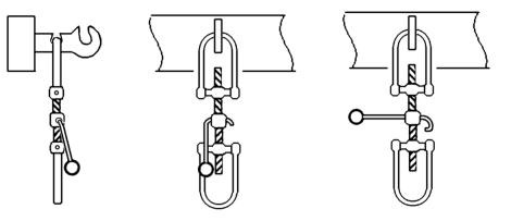
The second alternative, commonly used on goods stock which was
to be used in faster trains, was the 'instanter' coupling. First
patented in the 1890's this coupling was widely introduced in the
first years of the 20th century. In this system the centre link of
the three link chain was in the form of a distorted triangle, almost
a Y or T shape. In one position the longest side of the triangle
formed the link, in effect loose coupling. If the wagons were shunted
together however a shunter could move the link round until the
shorter side of the triangle formed the link. In this position the
wagons were held with buffers just touching, eliminating some of the
banging about when in transit.
Fig ___ Photo of a typical instanter coupling 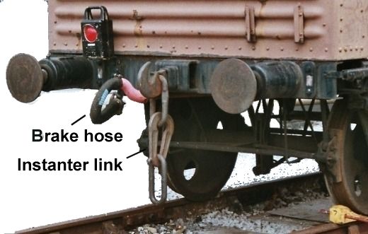
The instanter was cheaper than a screw coupling and
the goods yard shunter could use a long pole to flip the centre link
instead of climbing between the vehicles to tighten the screw
coupling (see Railway Company Goods Facilities - Introduction &Shunting Methods for a sketch showing this pole). Passenger shunters always had to deal with screw couplings,
a dangerous occupation as they had to get onto the track between vehicles, and this was one of the reasons they received
more pay.
Fig ___ Typical 'instanter' coupling 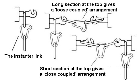
The instanter coupling was often fitted to express goods
vehicles, but it was not allowed to be used with passenger stock. The
law required a screw coupling to be used on coaches and the vehicles
attached to them. If two vehicles in such a train both only had
instanter couplings an 'emergency screw link coupling' would be used.
This was a separate standard screw-link coupling, without the hook of
course, which was fitted over the hooks on the two vehicles. The
diesel multiple units introduced by British Railways in the 1950's
carry a screw-link coupling to be used if the coupling between the
units broke. This could also be used if they broke down and had to be
towed by a goods locomotive or for when they pulled trailing load
(very rare in practice). These emergency screw link couplings are
mounted on a support in the guards compartment. They are painted red
so staff could tell they were the emergency type not a properly
fitted coupling.
Up to about the time of the First World War
all passenger stock, and goods vehicles likely to be attached to it,
were fitted with 'safety chains'. These were mounted to either side
of the coupling on the headstock so that if the main coupling failed
they would, hopefully, keep the train together until it reached a
station.
On early wagons the coupling was bolted onto the
headstock and when the wagon is on the move the forces on the
coupling will tend to pull the headstock off the ends of the
solebars. To get round this problem the 'spring bar' coupling was
developed in the mid nineteenth century (the GWR took it up in the
1890's). With this system the two coupling hooks are connected
together under the wagon by a long metal rod with a spring mounted in
the middle of the rod to absorb some of the shock when the coupling
tightens. With this system the coupling hooks were not bolted to the
wagon, the shanks of the two hooks passed though holes in the
headstock and were linked to the central rod. When the coupling was
placed under tension the rod pulled the far coupling hook against the
metal plate so the wagon was actually pulled or rather pushed along
by the force on the rear headstock, placing the chassis under
compression. The outer face of the headstock was fitted with a
protective metal plate through which the coupling rod passed.
Sometimes a rubber block was used instead of a spring (as
shown on the steel wagon chassis drawing above), springs can break
but rubber blocks although more expensive do not. The LNER favoured
rubber, other companies favoured springs but both types were seen on
all Big Four rolling stock.
The arrangement shown on the
steel chassis sketched above was called continuous coupling. The long
transverse spring shown on the wooden chassis sketch serves to
provide a degree of springing for both the coupling and the buffers.
This is discussed in more detail below but it should be noted that
the arrangement shown required additional joints in the coupling rod
where it attached to the springs, the arrangement shown was therefore
known as 'semi-continuous coupling'. This was frowned upon after the
1923 specification and the arrangement shown on the steel chassis
drawing above was more common on both wooden and steel chassis after
that date.
In 1923 the Railway Clearing House made continuous
coupling mandatory on all four wheeled and most six wheeled private
owner stock. Once again the railway companies adopted these
standardised parts to ease the maintenance of their stock when it
wandered on to 'foreign' company lines. On bogie stock or on dropped
centre vehicles continuous coupling was impractical so a 'self
contained' coupling was used, which had a built-in spring to absorb
the shock of starting.
There were alternative couplings, in
1873 an American inventor called Eli Janney patented an automatic
coupler (similar in general principle to the standard N gauge
coupling). This auto-coupler had a hinged jaw secured with a steel
pin, lifting the pin from the top allowed the jaw to swing open, a
scene familiar to many who have watched American films. The jaw had a
bulge that engaged with the pin, this bulge was called a knuckle and
hence the coupling is widely known as a 'knuckle coupler'. The other
common name is the 'Buckeye' coupling, this has nothing to do with
the design it is simply that the Buckeye company made most of the
couplings used and they cast their name into the thing. The knuckle
coupler became a legal requirement on all stock in America after
1893. These coupling were used in the UK, the LNER used them on some
passenger coaches for example, but automatic couplings in Britain
remained the exception rather than the rule until the later 1960's.
Following nationalisation British Rail retained the three
link, instanter and screw couplings but over the years a number of
alternative designs have been introduced to meet specific
requirements. As an example British Steel purchased a fleet of 100
ton bogie tippler wagons, designed to operate in fixed rakes on
regular runs from the docks to the steel works. These were fitted
with a special type of rotating coupling that allowed the wagons to
be turned upside down in a cage to unload them without uncoupling.
Freightliner developed its early container flats in the mid 1960's.
These were designed to operate in fixed sets of five vehicles and the
inner vehicles were fitted with a coupling consisting of a
rectangular bar with a square flange. The bar contained the air hose
for the braking system and the flanges were bolted together, as the
coupling was rigid no buffers were fitted. The outer vehicles had the
square coupling at one end but the outer end had a conventional screw
link coupling. These flats were lower than normal to allow them to
carry rectangular ISO size containers, they even had smaller than
standard wheels, so the outer vehicles had a raised buffer beam on
the end to carry the buffers at the regulation height above the
rail.
Passenger stock, particularly the multiple unit stock,
has seen an even wider range of couplings. I posted a question on the
uk.railways news group (actually regarding buffer stops) and the
following formed part of the replies -
There are now many
different types of couplers in use, Buckeye, tightlock, Scharfenberg,
BSI are all in use on Diesel and electric units in the UK. The London
Underground uses a different design on its passenger trains, Buckeyes
on its engineers vehicles, and older trains used to be fitted with
Ward couplers, I'm not sure if any are still in departmental use.
Brake and Steam Hoses
Wagons likely to be
marshalled with passenger trains often had a flexible connection for
the supply of steam from the loco. The steam was used for winter
carriage heating and on wagons the hoses were simply connected under
the wagon body by a pipe. Only banana vans and a few fruit vans
actually used this steam heating supply themselves, other stock just
had a through pipe.
With two kinds of continuous brake and
also the possibility of a steam pipe there could be two or three
separate flexible pipe connections on the end of the vehicle. Where
the vehicle was simply 'piped' the hoses were distinguished by colour
from those where a brake was fitted. The flexible connecting hoses
for air brakes, vacuum brakes and steam heating were physically
different, so no one could connect one to another by mistake.
On
goods stock the connecting hoses hung down from the buffer beam, on
passenger stock and vans intended to be coupled to them, it was usual
to fit a short length of solid pipe vertically on the end of the
vehicle with the vacuum pipe hanging from the top in a P shaped
arrangement. This was because the vehicles used 'screw couplings'
which required the shunter to stand on the track between the two
coaches or wagons to tighten the screw, this was dangerous enough
without having a length of rubber hose with a heavy metal connection
on the end dangling down. Having said which in some cases, such as
CCT (covered carriage truck) vans which had a drop down section at
the foot of the end door, it was not possible to fit the raised pipe
and the shunter just had to watch his head whilst working.
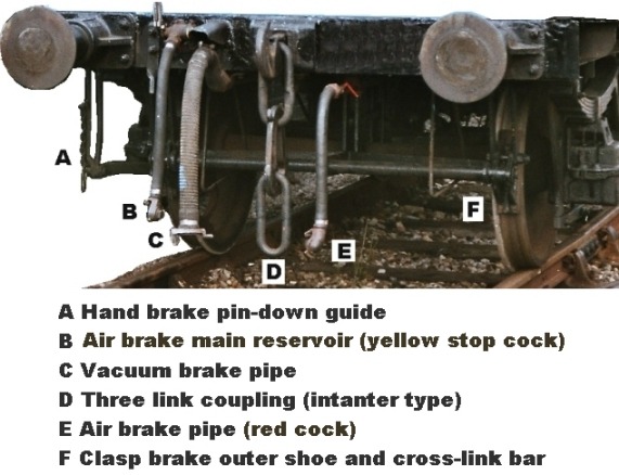
The picture shows a wagon which has both air and vacuum brakes, the air brake used is an older two-pipe system originally used by BR. This is actually the best design of air brake but many continental 'ferry wagons' were operating in the UK and these had only a simple single pipe system. Just one of these in a rake meant that the whole rake was operating as a single pipe system and BR eventually gave up their two pipe design. The air brake pipes are the smaller pipes in the photo (marked B and E). The left hand pipe feeds the main reservoir on the wagon, the one on the right is the train air brake pipe. If the cock and coupling on the train air brake had been white it would indicate that it was
simply a 'through' pipe, and the vehicle itself was not actually air braked. The thick ribbed pipe in the centre (marked C) is the vacuum brake pipe, for a 'piped' vehicle the coupling would again be white. A steam heat hose would be about the same diameter as the vacuum pipe, but smooth, not ribbed.
Fig___ Brake pipes on an early dual braked van.
^
Go to top of page
International Good Guys ~ Making the world a better place since 1971 ~ Site maintained by

All material Copyright © Mike Smith 2003 unless otherwise credited