Fig ___ Sketch of typical wooden wagon chassis
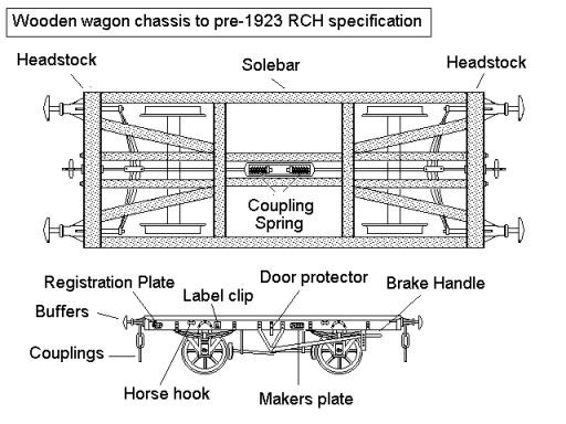
Chassis Construction
The chassis consisted of an oblong frame, called logically enough the
underframe, with a frame work of reinforcing cross-members inside it. The long
side members of the frame were called `solebars' and the shorter end pieces
were called `headstocks'. The wheels and brakes were fixed to the solebars and
the buffers and drawgear (couplings) to the headstocks. The underframes were
originally made of wood but over the years iron and then steel sections were
developed. Wooden underframes generally lasted about ten to fifteen years in
service, metal frames lasted a lot longer.
Fig ___ Sketch of typical
wooden wagon chassis
Note: The large transverse springs seen behind the headstocks
and the long rod running from end to end of the wagon are explained below in
the sections on couplings and buffers.
All wagons and vans were
equipped with somewhere to place the paper 'waybill'. The waybill is an
official document which describes the contents of the wagon, where it was
loaded and where it is to be unloaded. The most common method of securing the
waybill was a small label clip, generally mounted towards the bottom left of
the body, but sometimes fitted on the left end of the underframe. In either
case the clip had to be reached from the ground. On some older vehicles a small
wooden box was provided instead of a clip. On some stock a rectangular frame,
hinged at the bottom, was used. This had a metal grille across the front to
hold the label in place. This type was often fitted to the body side of a van
or open wagon, to the left of the centre but to the right of the other markings
on the side. The labels used in the label clips were sometimes white but more often pale brown,
pre printed with black markings and filled in with pencil. Loaded wagons would
normally have a label in the clip, a spot of white or light brown in the right location
serves well enough for this.
Also on the solebar would be the maker's
plate, usually oval or square, and the railway company registration plate,
which carried the railway company name and the vehicle number. The builders or
registration plates were often made in two different shapes to indicate
vehicles designed to use oil or grease axle boxes. They were usually painted
black sometimes with the lettering picked out in white paint. Some companies,
for example the North Staffordshire Railway, did not paint the vehicle number
on the side, relying on the cast registration plate for wagon identification.
The registration plate was supposed to be mounted toward the left hand end, but
some appeared near the centre of the solebar.
Horse hooks were fitted
near the ends of the solebars. On merchandise wagons (open wagons not used for
coal or other minerals) there would also be small hooks on the solebar or wagon
side for fastening ropes to hold the load in position and for tying a tarpaulin
to the wagon.
On wagons with a drop down side door there would also
often be one or two heavy metal straps projecting down from the sole bar to
stop the door trying to swing under the wagon and breaking its hinges. These
straps were called door protectors and there would be matching metal plates
bolted to the door itself. On some later wagons these simple protectors were
replaced with small sprung arms called 'door springs' attached to the wagon at
the bottom of the door.
The 'sandwich frame', consisting of a wooden
beam with sheet iron laid over the sides was originally used for locomotive
frames in the 1830's. By the 1840's the same idea was applied to goods rolling
stock where the wooden solebars were clad in iron sheeting. The result was a
flush sided solebar with just plan bolt heads showing where the running gear
and brake equipment was fitted. Several companies used this form of
construction in the mid nineteenth century, the GWR tried the idea for some of
their iron bodied goods wagons, but the sandwich frames were soon superseded by
all-metal underframes.
Iron underframes first appeared in the 1880's
and steel appeared in the late 1890's. The resistance to corrosion of the iron
underframe meant it was more popular than steel for many years. The solebars on
metal underframed wagons are usually [ shaped section, called 'channel
section', the flat side of the section was facing inwards to enable the running
gear to be bolted directly to it. A few companies had the flat side of the
solebar on the outside although this required hardwood packing pieces to be
fitted where the running gear was attached. From a modelling point of view
these resembled the sandwich frame construction with plain bolt heads showing
on the outer face. Some wagon chassis were built with I section metal, called
'bulb section', although again this required the wooden packing on the inner
face. These chassis were visually indistinguishable from the standard channel
section frames although technically the depth of the visible channel should be
slightly less. On metal underframes the 'horse hooks' mentioned above were
usually replaced by holes cast into the solebars.
Metal underframes
could be made physically longer and for a given strength they were lighter than
wooden frames, allowing long wagons and low centred vehicle or machinery
carrying wagons to be built. The Great Western Railway was at the forefront in
the development of iron underframes and the Great Eastern Railway was a pioneer
of steel underframes, by 1900 over half the GER wagons and vans had steel
underframes. The GWR switched almost exclusively to metal underframes by the
turn of the century but other companies, notably the post-grouping LNER,
continued building wooden underframed vehicles right into the 1940's.
Sometimes it was considered necessary to add an additional bracing
strap between the wheel supports under the wagon. These are called 'tie-bars'
or 'tie-rods'. Not all wagons of a particular type had these fitted, so you
will need to check photographs if modelling a specific wagon or van. They were
mainly associated with vacuum braked wagons and vehicles with a wheelbase of
more than ten feet. In N Gauge the (Hornby) Minitrix ten foot chassis has them,
the Peco and Graham Farish models do not. The design of the Peco wagon axle box
has a slight groove at the base, a length of 20 thou brass wire can be glued
into this groove using super glue or Araldite (you need to use pliers to gently
squeeze the rod into the groove as the latter is only about 18 thou wide). Care
should be taken not to get any on the inside face of the axle box or on the
wheels.
Fig ___ Sketch of typical iron or steel wagon chassis with
tie-bars
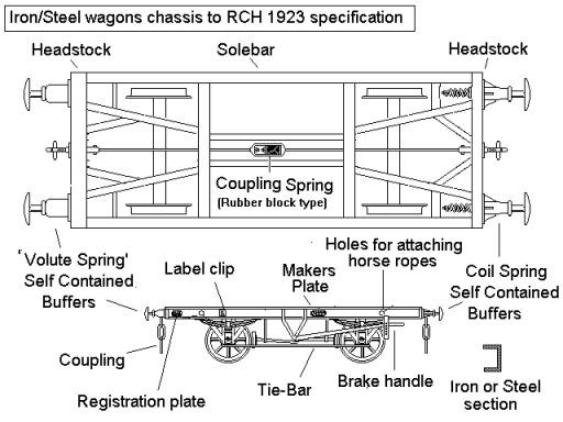
Note: The two ends of the chassis illustrated differ in the type
of buffer fitted. This would not normally be seen on a real chassis, the
illustration is merely to show the construction of the two types. The long rod
with the spring in the middle which runs from end to end of the wagon is
discussed below under 'couplings'.
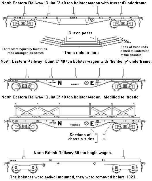
As vehicle length increases the
strain on the middle of the chassis increases but the tie-bar between the
wheels offers only limited additional strength to the wagon. There are two ways
a longer chassis can be strengthened; with wooden framed vehicles and early
steel framed vehicles the most common approach was to add an open frame
underneath called 'trussing'. Each truss consists of two posts called 'queen
posts', often reaching almost down to rail height, with a horizontal wire,
metal rod or strip frame connecting the queen posts together and reaching
diagonally up to the chassis at either end. A good example of this can be seen
on the under side of the Graham Farish open sulphate wagon. Prior to about 1930
most trussing used wire with bottle screws for tensioning, subsequently L
section steel strip was generally favoured. There would be a minimum of two
trusses, mounted on each side of the underframe towards the outer sides of the
chassis. For heavy loads four or even five trusses might be required. The
thickness of the rods used depended on the load the vehicle was designed to
carry. On the Graham Farish bogie van, which uses the same four truss chassis
as the sulphate wagon, the truss rods should be much lighter in section. You
might consider removing the centre pair of trusses entirely and replacing the
horizontal moulded rods between the queen posts on the outer pair with fine
fishing line but this does take some care and patience.
The alternative
approach for long wagons or heavy loads is to make the solebars much deeper and
if you look at wagons such as the Lowmac machinery wagons you will see that the
solebars are nearly twice as deep as those on the standard steel framed
chassis.
Increasing the depth of the solebars on a flat chassis with
standard wheel mountings raises the floor height. As the clearance under
bridges and the like is fixed this reduces the height of the cargo the wagon
can carry. The only wagons I know of which used this approach were some four
wheeled thirty ton capacity 'pig iron' carrying wagons built by British
Railways. On these the load was never going to be very high so the raised floor
was not a problem. The deep section on the solebars of these wagons only
extended between the wheels, the ends of the solebars outside the wheel
mountings were of normal section, introducing a 'step' in the shape (modelling
these wagons id discussed in the section on Kit Bashing).
For longer
vehicles, supported on bogies, it is possible to vary the depth of the solebar
along the length of the vehicle, making it deeper in the centre and narrower
above the bogies. This shape, commonly called a 'fish belly', keeps the overall
height of the vehicle deck constant but allows much heavier loads to be
carried. It is confined to steel underframed stock and the wagon builders had
to wait until steel rolling technology improved before they could use the idea.
The earliest wagons I know of employing this structure date from shortly before
the First World War.
The depth of the centre section used depends on
the load to be carried. In the sketch below the North British fish-belly wagon
was designed for thirty tons, the North Eastern Railway vehicle for forty tons.
Note that, just to confuse the unwary, the NER built versions of their five
bolster 'Quint C' wagon with both trussed and fish-belly chassis. Some of the
latter were fitted up with steel frames called trestles to carry large sheets
of metal.
Fig ____ Chassis for long or heavy load vehicles.
Modelling these three types of chassis is possible, the trussed
underframe being the most difficult. This is discussed more fully in the
section on Kit Bashing. There are several kits on the market and of these the N
Gauge Society pre-nationalisation Bogie Bolster D is a personal favourite. The
model is in plastic and a little care is needed to keep it flat during assembly
but the result is worth the effort. Unfortunately most ready-to-run Continental
models have a series of V shaped frames with a central truss rod which does not
look right for British use. One exception is the Bachman 'old timer' chassis,
which scales out to just over thirty feet in British N. This lacks buffers and
neither the 'stake car' (a flat wagon with posts mounted along the sides) nor
the 'gondola' a bogie five plank open wagon) resemble any specific British
prototype that I know of, but the former fitted with buffer beams cut from
redundant Lima chassis and bolsters served well on a light railway layout. The
chassis consists of a metal bar onto which the bogies are mounted and the body
is a simple clip-fit onto this. This leaves space at the ends to allow the
gluing in of the buffer beams. There are two continental models with the
fishbelly chassis, the Roco bogie wagon reference 2352S (a scale 41 feet or
12.5 m long) and the Kadee fifty foot wagon reference 45100 (a scale 46 feet or
14 m long). Neither of these is ideal for any particular British prototype but
they can be fettled into something which captures the general appearance of
various British prototypes.