Signals -
Mechanical Types & Fog Signals
Railway signalling is part science
and part art form, it has always relied heavily on dedicated staff and in the
early years on the memory of train crews. For details of the ways signals were
actually used to control traffic movements see the section on Communications
& Traffic Control. This section deals with the appearance and construction
of the signals.
It is impractical to cover anything more than the
basics of appearance here and the reader is recommended to track down reference
books for their particular company. One source is of particular note; the small
Peco publication 'Signalling the Layout' gives all the basic
information required. The website at signalbox.org provides a lot of
information on prototype signalling including numerous illustrations of the
equipment used. One small point worth mentioning is that in railway signalling
parlance the term 'ahead of' means the track past the signal, the
word 'behind' or in 'rear of' means the track before the train
reaches the signal. This is often a source of confusion for modellers trying to
make sense of official instructions.
The 'bobbies' (signalmen)
and gate-keepers at the level crossings first used hand signals, hand-held
flags and hand-held lanterns to signal to the train crew. On the railway a
white flag or light meant all-clear, red meant danger or stop and green
originally meant caution. With the increasing use of gas and electric white
lights the significance of green changed to all clear as of about 1893. As with
most changes this took several years to apply, the GWR adopted green for
all-clear in 1895 but green was still occasionally associated with a cautionary
warning until the 1960's. From about the time of the First World War a
white light was sometimes used as a danger indication on small track-side
signals, discussed below.
Mechanical signals first appeared in about
1834 but there was no common standard. The pointed board signal illustrated
below was developed by the Liverpool & Manchester Railway and became the
first standard. When turned to face the driver it meant danger or stop, when
turned edge-on to the driver it meant all-clear. The Great Western Railway
initially used the same design but had a third option of turning the rear face
of the board, painted green, toward on coming traffic to indicate
'caution'. In 1841 several companies held a meeting to discuss
signalling and agreed to adopt the colours used by the L&MR to indicate
'danger' (red), 'caution' (green) and 'all clear'
(white). Three options were required as most lines at the time were operated on
the 'interval' system of working discussed in the section on
Communications & Control Systems.
Signal designs remained many
and varied for quite some time, some systems like the L&M board and the
later square iron 'flag' type only giving an indication of danger, no
positive indication of all clear. Another popular nineteenth century railway
signal employed a circular disc, when turned edge-on and hence not visible it
meant all-clear, when turned to face the engine driver it meant stop. If the
board, flag or disc fell off its mounting the train crew might not realise it
was missing and assume all was well.
The Brunel disc and bar signal
appeared on the Great Western Railway in 1840, this had a circular disc about
four foot in diameter mounted above and at right angles to a flat bar about
eight foot long. When turned so the disc faced the train driver it meant
all-clear, when the bar was visible the train had to stop.
Disc and bar
signals of various designs were used on several railways, including the
Somerset & Dorset, the North Eastern Railway, the Furness Railway and the
narrow gauge Ffestiniog Railway, they remained in use in some locations until
after the turn of the Century although later designs used smaller discs and
bars. Signalling is not however a simple matter of stop or go and variations
were introduced on the disc and bar and other systems to indicate such things
as which route was being signalled.
There were also signals using balls
and kite shapes, hoisted up masts beside the track. These were first used in
Britain in 1840 and came from shipping where wicker basket-work shapes are
still used today (for example a single black ball, about two foot in diameter
suspended from the foremast means the ship has anchored). On the railways the
ball hoisted up the mast indicated the 'all clear' so that if it
failed (i.e. the ball fell off) the train would stop. This offered a 'fail
safe' system which found favour with the French and the Americans. The
term 'highball' meant a line which was clear ahead and American
express passenger services are still sometimes referred to as
'highball' trains.
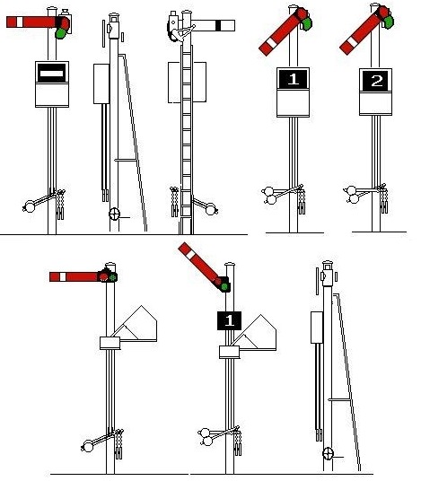
The drawings show an early 'fishtailed
board' signal, where the entire post was turned, an early 'flag'
signal (the flag is in fact an iron plate), and a 'ball' signal. The
lower drawings show a Brunel disc and bar (the T shaped ends on the bar
indicate it is a level crossing signal) and a Lancashire and Yorkshire Railway level
crossing double-disc signal. In each case the signal on the left indicates
danger, that on the right shows all-clear.
Fig___ Early signal
designs
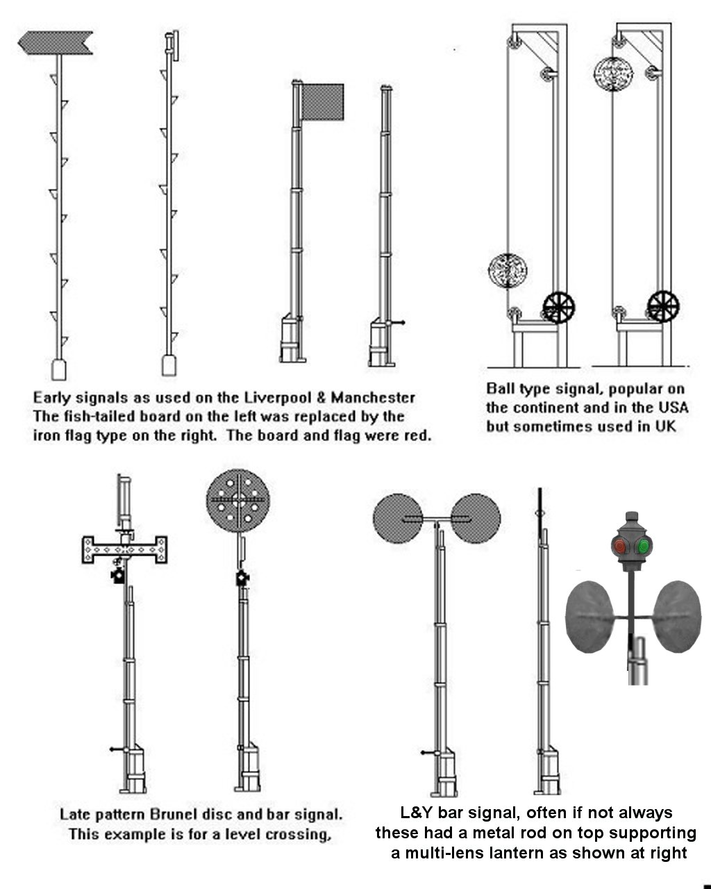
Thanks are due to Neil Mackay for pointing out that the signal bottom right was L&Y not NER - He has a book out on NER signals: A History of North Eastern Railway Signalling bv Neil MacKay - published by the NER Association
It
is doubtful if many of these early signals survived much beyond 1900, at least
on main line railways. On remote branches and industrial lines however
non-standard signals survived into comparatively recent times. A Brunel disk
and bar type as shown above was in use at a level crossing on a running line in
the Forest of Dean into the 1920's and one, again on a running line,
survived (unused) in the same area into the 1950's.
The Midland
Railway used a diskless bar type signal for shunting or blasting signals, this
was adopted by the LMS (who built a few with their standard tubular metal
posts) and remained in widespread use into the 1960's. They were used in
yards where two sidings crossed one another and there might be a risk of
collision and also on lines feeding quarries. In the yard the signal meant stop
if the bar faced the driver, on the quarry line the bar was turned sideways to
indicate that blasting was in progress. The arm had a multi-lensed oil lamp
mounted on top to give an indication at night (signal lights are discussed
below). On the Midland example the counterweight for the signal was mounted at
the base of the post with a rigid rod mounted diagonally across the post
operating the signal.
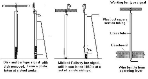
The signal in the lower left of Fig___ was
originally a disk and bar type but the disk had at some point been removed,
note the unusual placing of the counterweighted arm near the top of the post.
This was still in use in the 1970's on a (steam operated) internal railway
at a large steelworks.
One point to note is that modelling a working bar
or disk and bar signal is relatively easy, simply use a length of brass tube
mounted inside a square section Plastruct tube with a brass wire passing up
through the middle attached to the signal arm. The lower end of the wire can
extend down through the baseboard where knob or just a simple bend would allow
it to be operated.
Fig___ Bar type signals in recent use
In the
1790's a French clergyman by the name of Claude Chappe developed
signalling system for passing messages between cities. This system was based on
naval 'semaphore' and used tall towers on which were mounted pairs of
swinging arms which were visible over considerable distances.
This
system worked well and in 1841 Charles Hutton Gregory (chief engineer on the
London & Croydon Railway) erected the first railway semaphore signal at New
Cross (close by 'Telegraph Hill' which had a Chappe type semaphore
signalling tower on top dating from the 1790's). Other companies
recognised the value of this simple but effective signal and they spread quite
rapidly across the system.
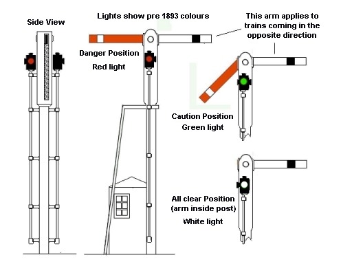
Early semaphores were many and varied, most
designs used a post with a slot, when the signal arm was down inside the post
it meant all-clear, at 45 degrees it meant caution and when lifted to the
horizontal it meant stop. The drawing shows a basic slotted post semaphore
signal and this design had arms for both directions on a single post, the
convention was that the driver looked at the arm on the left of the
post.
Fig___ Slotted-post three-position semaphore signal with
'policeman's box'
The problem with the slotted post signals was that the arm could jam inside the post, and if the arm fell off the signal was left showing the 'all clear'. From the 1950s the rules required that the signal arm was always visible, bringing the common two-position signal in which the arm is always visible.
Early semaphore signal arms were of many shapes and
sizes, where the posts were mounted on top of signal boxes the arms could be
quite large, perhaps eight foot long by a foot or more high, but the most
common designs settled on arms of about three or four foot long. The GWR, which
had developed the disk and bar type signal for it broad gauge lines, replaced
them quite rapidly after 1870 with semaphore types.
Fig___ Signal arm reverse faces.
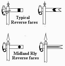
The front face of
the semaphore signal arm (facing the driver of the train) was painted red and
the reverse side was painted white. At some point (I believe in the late
1850's) a white stripe was added near the end of the front face and a
black stripe was added to the reverse. Some companies used white and black dots
in place of the stripe and some companies used a horizontal stripe on the
reverse face, the Midland Railway is one example.
On lines where trains ran at night a
lantern could be mounted on the signal but on most types of signal this had to
change colour when the signal position changed. Early systems used lanterns
with multiple coloured lenses which were rotated by a linkage to the signal arm
to show the appropriate colour to the train crew. In the early years oil lamps
burning whale oil and even candles were used in these lanterns (the Great
Northern Railway used candle power until the 1870's when a petrol lantern
was introduced). Paraffin had been named in 1830 by a German chemist (actually
the liquid we call paraffin is technically Kerosene) and in the later
1830's paraffin lamps augmented the whale oil lamps used on signals. The
early lamps were thirsty beasts, average consumption of oil was in the order of
twenty gallons of oil per lamp per year.
As these
early lights did not last very long and sometimes were blown out by the wind
they were sometimes mounted lower down the post where they could be easily
reached. Quite early on a long-life paraffin lamp was developed which would
burn unattended for eight days, a 'lamp man' was employed to changes
these lamps once a week. In the early part of this century the design of the
burner was improved, reducing each lamp's consumption to about eight
gallons per year.
Fig___ Signal & Telegraph Dept. Lamp Man
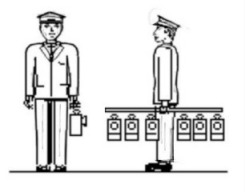
Paraffin lamps, sometimes called 'oil
lamps', continued in use into the 21st century as running cables to the
older semaphore signals added a lot to the cost. Electric lanterns are
sometimes used on more modern semaphore signals. There was a discussion on a
news group on this topic, from which I gather than a common option is 12 volt
usually 5 watt lamps fitted as these are about the same light as an oil lamp.
Other contributors mentions some lanterns running on 110v. However where
relevant to the layout signalling a lamp-man walking along the track would add
a little interest.
The light on early (pre 1893) three position signals
showed red for danger, green for caution and white for all-clear but, because
the paraffin lamp produces a rather yellow light, the 'green' lens
was blue glass, which gives a green light.
In 1844 the Railway
Department of the Board of Trade was established, and this organisation
subsequently had to approve all proposed signalling systems. This brought a
degree of standardisation but by this time there were a great many signals in
place, and with every change in signalling practice it took time to replace or
convert the older equipment.
The early signals were all locally operated
by the 'bobby' who was usually provided with just a small hut or
shelter, resembling a military 'sentry box', about the size of the
modern 'porta-loo' used on building sites. By the 1850's signal
boxes had appeared, operating remote signals using wires and pulleys, but it
was some years before the signal box system was widely implemented. Signals
could be mechanically operated out to a maximum of about half a mile or so from
the box using only the strength of the signalman's arms.
The three
position slotted post signal was not a great success, the 45 degree
'warning' position was difficult to operate reliably and most larger
railway companies abandoned the 'caution' position, changing to a
two-position system of horizontal for danger and vertical for all clear. The
slotted post design remained in service on some minor lines for many years,
notably on the Isle of Man railway system. Such a signal would not be out of
place on a 1930's light railway, although these would probably be
two-position signals, horizontal for danger, inside the post for
all-clear.
The rotating multi-lens lamps on signal posts were prone to
failures and in 1854 Stephens & Sons signal company introduced a
two-position signal with the arm mounted on the side of the post. The arm was
set to horizontal for 'danger' and angled down at about forty five
degrees for 'all clear', this design meant that if the signal arm
fell off the driver would not see it as indicating 'all clear'. The
lenses for the lamp were mounted in a kidney shaped frame called a spectacle
plate attached to the end of the signal arm, eliminating the need for a
rotating lamp.
This idea was soon adopted by most companies but some
preferred to mount the lamp and its associated lenses separate from the signal
arm and lower down the post where they were closer to the drivers line of sight
and more easily serviced. The Furness Railway was another company which stayed
with the slotted post signals, although these used the horizontal position for
danger and a downward angle of 45 degrees for all clear. Unusually the posts
themselves were of metal lattice construction. As a result of the design of the
mounting it was impractical to have the lamp and spectacle plate mounted on the
end of the arm and these were fitted separately lower down the post. A few of
these signals with low-mounted lights and lenses remained in service into the
1930's and rare examples (notable the Furness Railway types) were still in
use into the early years of BR.
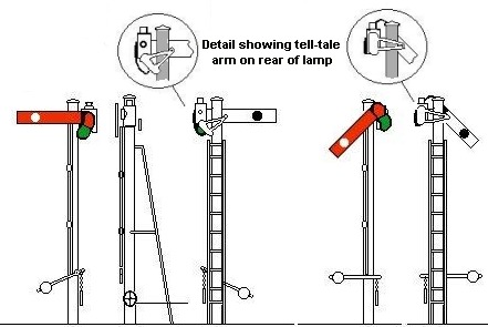
If the signal could be seen from the
signal box a small lens was fitted on the rear face of the lamp and a moving
metal plate was added which covered the light when the signal was set to
all-clear. This allowed the signalman to check the signal lamp was lit and the
arm was correctly positioned at night. The sketch below shows this plate.
Fig___ Early two-position signal
(The drawing is
based on a Cambrian Railways original)
In some early designs of
two-position signal the arm was not weighted and if the signal cable failed the
arm could fall to the all clear position. This was evidently a design flaw and
a common solution was to make the kidney shaped 'spectacle plate'
heavy enough to do the job. The major railway companies adopted this safety
feature but is was several years before the Railway Department of the Board of
Trade made it mandatory, and that was only after a serious
accident.
Most of the early semaphore signals were two-position types
with horizontal for danger and angled down for all clear, these are referred to
as 'lower quadrant' systems. Some early signals of the side mounted
type used three positions as before; horizontal for danger, almost vertical for
all-clear and forty five degrees for caution. These new side mounted signal
arms thus required a three-lens spectacle plate for the three positions, three
position semaphore signals were very rare in Britain but were sometimes seen in
America.
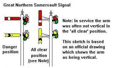
In 1876 there was an accident on the Great Northern Railway
caused by driven snow jamming a slotted post signal with the signal arm inside
the post. Following the accident the company developed a new type of signal,
called a 'centre pivoted arm' or 'somersault' signal. These
first appeared in late 1876 and were all of the two-position type. Somersault
signals gave a very clear indication and the somersault design was used by
several companies, notably in South Wales on the Taff Vale, Rhymney Railway,
Barry Railway and the Brecon & Merthyr Railway and on the Midland &
Great Northern joint railway in Norfolk.
Fig___ Somersault Signals
On the
early railways the driver of the train pulled up as soon as he could after
passing a signal set at danger. In 1846 the adoption of remote controlled
signals allowed a change in the rules and the train had to stop at or
immediately before reaching the danger signal. This brought in a need for a
secondary signal, usually called a 'distant', to pre-warn the drivers
that the next signal might be at danger. The 'stop' type signals were
thereafter referred to as 'home' signals. Distant signals are usually
placed about half a mile down the track before the home signal.
The home
signal and indeed any 'stop' signals on a running line would if
possible be placed where they would stop a train 'behind' (that is
before it passed) the signal box, so the signalman could give hand
signals to the crew in the event of a signal failure.
Signal arms were
painted red on the side facing the approaching engine and white on the reverse
side. The red side had a white strip or dot, the white side had a black stripe
or dot. Distant signals were originally not distinguished from home signals by
shape or colour, the driver had to remember whether the signal was a stop
signal or a warning signal. In the early 1870's the London Brighton &
South Coast Railway introduced 'distant' signals with a V shaped end
to the signal arm, but they were still painted red with a white bar on them. In
1917 the Board of Trade decided that all distant signals should have the V
shaped notch in the end.
The lights on distant signals were still
showing red for danger and green for all-clear, the yellow light (replacing the
green) was introduced on the Great Central Railway two-position distant signals
in 1917 and was soon adopted by other companies. The Great Northern Railway
adopted this yellow caution light and they then started painting their distant
signal arms yellow with a black stripe. By the mid 1920's most companies
distant signals had yellow fronts on the arm and red and yellow lights but it
was the mid 1930's before all the older signals were
converted.
There were still variations in signal arm colours, for
example the Midland Railway, South East and Chatham Railway and the Cambrian
Railways all used a circular spot in place of the vertical stripe on their
'home' signals. Some companies, including the Midland Railway, used a
horizontal line along the length of the signal arm in place of the more common
chevron design on their 'distant' signal arms.
In 1876 the
Board of Trade Railway Department decided that signal arms for different tracks
should be mounted on separate posts. To save on space the railway signalling
engineers developed the 'bracket signal' which had a single
supporting mast topped by a platform on which there would be two or more short
signal posts.
This was building on the work already done on signal
gantries, which are bridge like structures supporting a row of signal posts
above the tracks. Gantries were expensive compared to bracket signals and were
usually only seen at major railway stations where many tracks ran
parallel.
Early gantries were built simply, if sturdily, of wood but by
the 1870's metal casting had improved and iron structures were being
produced. Early bracket signals used these new cast iron supports for the
platforms, usually based on cast circles and arches all bolted together. These
castings were heavy and added to the wind resistance, so by the 1920's all
companies had switched to lighter structures based on light metal strips called
a 'truss' design.
Bracket signal masts were adapted to
position a single arm in clear view where normal sighting might be difficult.
As an example if there was a large water tank beside the track where the signal
had to go the bracket could be jutted out over the track placing the signal arm
in clear view.
On multi-arm bracket signals and gantries the convention
was that the tallest post referred to the most important route, so for example
if approaching a junction where a branch line left the main line the signal
post for the main line would be slightly taller than the post for the branch.
This convention became a problem where under-slung signals were used.
These were signal arms suspended from the under-side of a bracket or perhaps
fitted under the awning of a platform canopy. They were used where some
obstruction, such as a bridge, or the platform canopy, would make sighting a
normal height signal difficult.
Fig___ Bracket signal and signal
gantry
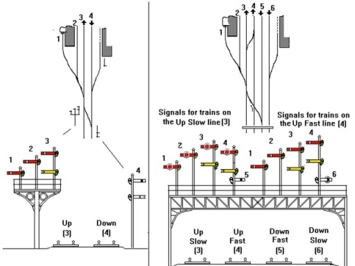
The drawing on the left shows a bracket signal controlling
the approach to a station with loop lines for the platforms and a bay platform
as well. The numbers next to the signal arms indicate which of the tracks they
apply to on the small track-plan above. The support for the brackets is of the
older cast iron type.
The sketch on the right is a gantry, this uses the
later 'truss' type supporting framework made up of oblong frames with
a diagonal 'truss'. The gantry makes sense in this case as now there
are two double track lines, the centre pair of lines are for fast trains, the
two outer lines handle the slower local trains and goods traffic. This
arrangement was particularly useful on outer suburban lines where frequent
stopping passenger services ran on the outer slow lines leaving the centre fast
tracks for express trains. Note that an alternative arrangement for the fast
and slow lines was to have them arranged as two double-tracks side by side. In
the drawing shown above the lines on the left would be the 'fast' up
and down lines, those on the right the 'slow' up and down lines. This
arrangement would require an island platform in the station to handle trains on
the centre two lines.
The signals facing you all apply to the
'Up' lines, the circles on the signal arms for the 'Up
Slow' line will be explained later. With the ability for trains to cross
from the up-fast to the up slow and vise versa each set of signals has posts
for both the fast and slow lines, as these are 'through' lines the
posts have a second 'distant' arm on them as well.
Ratio offer
an excellent kit of a truss type gantry however they do not supply any posts or
arms with the kit so you need to add those either from Ratio kits or from
home-made parts.
With very few exceptions where you see two arms on a
single support they both apply to the same track and the lower one will be a
distant signal, giving advanced warning of the next signal on the line. The
exceptions are occasional signals with one arm facing each way on a single post
(but these were rare) and signals on goods loops. The signal gantry shown above
has two arms for the Down lines on the reverse side of the posts (signal arms
numbered 5 and 6 on the drawing).
Goods lines were not covered by the
bracket signal rules and some rare examples of multi-armed single post signals
survived into the 1960's although these double home signals only appeared
near points, the upper arm always referred to the track diverging to the
left.
To save on the expense of multiple signals a 'route
indicator' might be used, these had a separate box which displayed a
letter or number to indicate the line the signal arm was currently controlling.
For example a single armed signal on the approach to a station might have an
indicator to show whether the signal was set for the bay platform or the
through line. They first appeared at about the time of the First World War and
the principle remains in use today.
Mechanical route indicators would
normally be on a single post signal and there were various designs in service.
The GWR and some other companies employed a shallow metal box about eighteen
inches square and perhaps six inches deep, bolted to the post about three
quarters of the way up. This box was normally painted black and contained
cut-out metal letters and/or figures. The LMS had a design in which the plates
were laid off to one side at an angle and were shifted into the vertical
position to be displayed. Personally I would suggest the plain box mounted
square on the post, which seems to have been in widespread use, is the easier
to model.
These mechanical route indicators might be seen on the
'starter' signals on the platform ends at a terminus, or in goods
yards where the driver might be facing a range of complex point-work. They did
occasionally appear on running line signals at the approach to a station, but
they were associated with lines where speeds were slow so this would normally
be a terminus rather than a through station.
The 'works'
underneath the indicator box were sometimes open to view, a series of small
levers for each letter or number with rods passing up into the box itself. On
passenger platforms and on running lines it was normal to box all this in to
avoid accidents to inquisitive passengers, the drawing shows such a
'boxed' arrangement. Note the multiple weighted levers at the base of
the post.
Fig___ Typical mechanical 'Route
Indicator'
At the signal box there would be several levers associated with
this signal, all of them would operate the signal arm but each lever would
cause a different letter or number to rise up in the box and be displayed,
indicating to the driver which route the signal applied to.
As an
example a small country station might have a junction with a branch line, the
'route indicator' on the single signal post might then be used to
indicate whether the points were set for the main line or the branch. All of
this was protected by mechanical or electrical 'interlocking', so the
signal lever could only be pulled after the appropriate points had been set.
Mechanical interlocking of points and signals was invented in a crude form by a
French engineer but the fully mechanically interlocked signal frame was
patented by John Saxby in 1856 and the first installation was at Bricklayers
Arms Junction. Interlocking of signals and points meant that signals can only be set when the points are in the right position, in 1889 the Regulation of the Railways Act made interlocking mandatory.
Modern electric colour light signals also use route
indicators to indicate the point settings. These are covered later in this
section.
By the turn of the century only four companies made their own
signals; the Great Western, the Midland, the London & North Western and the
Lancashire & Yorkshire. Everyone else used one of the large independent
companies; Saxby & Farmer along side the LNWR line at Kilburn, Stevens
& Sons in Southwark who supplied most of the Southern lines and in the
North the Railway Signal Company based at Fazakerly, close by the L&Y main
line.
The LNWR had used Saxby & Farmer until a row between their two
managing directors lead to the building of a signal works at Crewe, and the
L&Y had originally used the Railway Signal Company products and continued
to build very similar equipment when they opened their own signal
works.
The supply of signalling equipment on the Scottish lines was
split between just two companies; the Highland Railway used McKenzie &
Holland, everyone else used the Glasgow factory of Stephens & Sons. Saxby
& Farmer and Stephens & Sons were the two really big names in
signalling and their products were used by most of the smaller lines.
In
1911 a group of eight railway company signalling experts met to discuss the
various problems and in 1913 the Institute of Railway Signal Engineers was
founded. In the 1920's the Institute recommended that the warning position
on the three-position signals be abandoned due to its unreliability. Most
companies had abolished the caution position in about the 1870's but there
were still quite a few old signals dotted round the country on minor lines and
these were changed to two position operation.
In 1910 the two-position
'upper quadrant' signal appeared, which had the advantage of lighter
construction. A horizontal arm still meant danger but the all clear was
represented by the arm pointing upwards at 45 degrees. This design was adopted
in the 1920's by the post-grouping London Midland & Scottish, the
Southern Railway and the London North Eastern. The LNER began replacing the
Great Northern somersault signals with new upper quadrant types in about 1923,
although some of the latter remained in service for many
years.
Fig___ Typical upper and lower quadrant signals
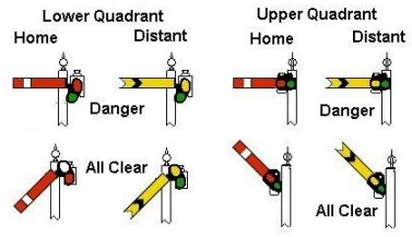
The GWR retained its own in-house
lower quadrant design, they tried a three position upper-quadrant signal to an
American design at Paddington station but this was the only example of its
type.
The railway department of the Department of Transport decided that
all the railways should switch to the upper quadrant design sometime in the
1930's and most companies complied as signals fell due for replacement or
major repairs. Some companies, such as the Great Western Railway and the
Cheshire Lines Committee, continued to use the two-position lower quadrant
signals. In the mid 1980's British Railways decided to replace the
remaining lower quadrant signals (mainly confined to the old GWR lines) with
colour light signals as they fell due for servicing. However there were still
lower quadrant signals in use in the first half of the
1990's.
Originally signal masts or posts were of round section
wood, and were often quite tall. By the middle of the 19th century square
section wooden posts were common, although in Scotland all the companies used
metal lattice masts. Company-built signals were often quite distinctive, most
posts were of the square section wooden variety but the LNWR favoured heavy
section square posts and the GWR used a slender tapered square post. The wooden
posts required some form of cap called a 'finial' on the top to
protect the end grain from absorbing water, and these were also often of
distinctive design. The Midland Railway had a large ornamental spike, several
lines including the GWR used variations on the ball and spike design, whilst
the LSWR had a distinctive tall spike on theirs.
Considering the
equipment from specialist signalling suppliers McKenzie & Holland had a
tall spike about three and a half foot tall whereas Stephens & Sons used a
more or less standard eighteen inch high ball and spike. In the South of the
country signal posts were sometimes built from rail and carried a small square
finial on top. These rail-built signals were common in the South by the
1920's.
Also in the 1920's tubular steel posts and square
section concrete posts appeared, the latter being common on the Great Northern
Railway's 'somersault' type signals. The concrete posts were
solid for about the lower third but the upper two thirds were pierced through
with oval shaped holes to save weight (see Fig___ below). Concrete signal posts
were not the usual bright white, they may have started out white but concrete
is absorbent and exposure to the soot and grime of the railway soon toned this
down to a grubby grey. Although the Southern Railway made great use of pre-cast
concrete, mainly from the Exmouth Junction Concrete Works, they did not favour
concrete signal posts preferring to use posts made from lengths of
rail.
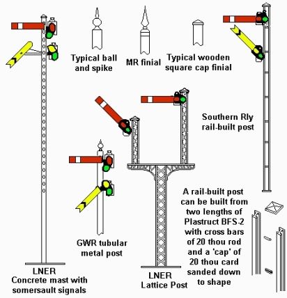
The Ratio OO range includes GWR, LNER, LMS types and SR (rail
built) types, their rather more limited N Gauge range models appear to be of a
GWR type square section wooden mast. P. D Marsh offer lattice post signals in N
gauge, although these whitemetal mouldings are heavy they do capture the
general appearance rather well. The SR rail built signals can be knocked up
using Plastruct I section reference BFS-2 as shown in the drawing. Modelling
the concrete post type would take a bit of patience. First take a piece of
Plastruct I section (BFS-2) and mark up the centre web where the slots will be.
The slots are slightly shorter than the width of the signal arm and there are
about twenty three of them. Now use a pin or needle held in a pin-vise to
scrape through the centre web to make the required holes. Mark the sides of the
strip to show where the holes are (pencil will do for that or just make a small
scratch with the pin). Wipe a little solvent into the web to attack the surface
and form a 'key' and fill the slot on each side with fine grade
Milliput. Whilst the putty is still wet poke through the holes with the pin (do
not worry of you get lumps building up around the holes) and leave the thing to
dry. When the putty has set solid (I would allow a day for this) sand the thing
smooth and paint with a 'dirty grey' mix. There were a few cases
where the somersault signal arms were replaced with standard LNER upper
quadrant signals but the old concrete post was retained. Making just one such
post helps identify the location and the remainder of the signals can be of a
standard type made up from kits.
Fig___ Various companies designs for
signals
Where the positioning of the
signal was awkward, such as when close to an over bridge or where background
clutter made sighting difficult, some companies employed very tall signal
posts, up to sixty feet high, which could be seen against the clear sky and
over any local obstruction. These so called 'sky light signals' were
more common in the North West than elsewhere and some survived into the
1980's. The LNWR had some particularly fine examples, often with a
duplicate or repeater arm mounted low down on the post where it could be more
easily seen as the train drew close. In the mid 1980's new Health &
Safety legislation was enacted which made these very tall signals illegal, some
were replaced with standard British Railways nine foot tubular steel signal
posts, but in many cases the opportunity was taken to install the new colour
light systems.
The station at Hale in Cheshire had one of these tall
signals on a lattice mast with a low-mounted repeater arm close by a road
over-bridge. The sketch was made from a rather poor photograph I took in about
1983. This signal was replaced by a standard British Railways upper quadrant
semaphore on a nine foot tubular post in the mid 1980's, and then the
whole section was converted to colour light signalling in the early
1990's.
When one of these tall signals was used because of
background clutter, rather than for sighting over a bridge, the associated lamp
was sometimes not mounted at the top but was fitted lower down, where it could
be more easily seen at night and more easily tended. The spectacle plate was
obviously not attached to the end of the signal arm in this case, instead it
was a separate item mounted on a small pivot in front of the lamp.
Where
there was a problem with a cluttered background, but a tall signal was either
impractical or contrary to company policy, another option was to mount a
section of white painted board behind the signal arm so it could be more easily
seen or, if the background were owned by the railway (such as a bridge over the
line) a white square or quadrant could be painted on it to make the signal more
visible.
The third option was to mount a remote 'banner
repeater' signal in an easily seen position which mimicked the main
signal. The standard design for a banner repeater was a circular disk of
translucent material with the signal arm, blunt ended for a home signal,
fish-tailed for a distant, painted on in black. Mounted behind the disk was a
lantern for night visibility and the disk was electrically or mechanically
linked to the main signal so that it operated in concert with the signal arm.
The lanterns used were physically larger than those on normal signals, the GWR
favoured tall cylindrical lamps, the electric unit on a signal still in use at
Stockport has large square lamps with a big circular reflector on the front.
The GWR posts were painted a dark colour, the signal at Stockport is all-
white. It is perhaps worth noting that the banner repeater operated in the same
quadrant as the normal signals on the line, hence GWR banner repeaters were
lower quadrant whereas the LMS, LNER and SR favoured upper quadrant.
You may
wonder why the signal itself was not positioned where it could be seen, one
reason might be that the signal proper, and any train stopped at it, would not
be visible to the signal box staff. The banner simply gave an advance warning
in case a signal was at danger, the train did not stop at the banner but only
when it reached the proper signal. There is a banner repeater signal on the
line from Altrincham to Stockport where the line joins the main Manchester to
London tracks. The line curves tightly and passes under a road bridge at this
point, out of sight of the signal box.
Fig___ Sky signals,
painted board signals and banner repeaters
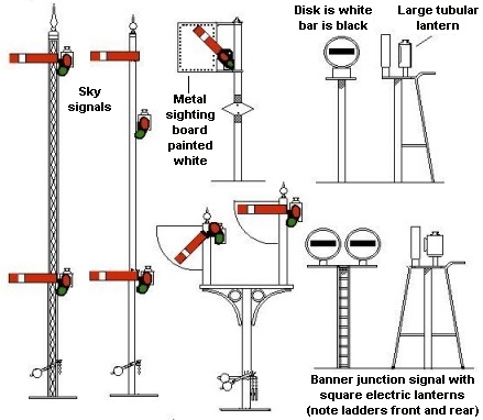
The sketches in Fig___ are all taken
from photographs, the forty foot tall lattice mast signal was in place at Hale
near Altrincham in Cheshire into the 1980's. The wooden post sky signal
with the separately mounted spectacle plate is based on a GWR broad-gauge
signal photographed just before the change to standard gauge.
The upper
quadrant signal with the metal sheet was photographed in 1986, on this signal
the ladder went right to the top of the post and the rivets holding the plate
to the supporting frame had rusted, showing black against the white sheet. The
diamond shape on the post indicates that the line is protected by electrical
'track circuits' (these are discussed in detail later).
The
junction signal was photographed in the 1940's on the GWR system, the
sheets appear to be wood but it is difficult to tell from the photo. The single
banner signal is sketched from a photograph in a book on GWR signalling by
Adrian Vaughn (for details of which see the bibliography) and the double banner
is drawn from a signal still in use on the line from Altrincham to the junction
with the main line at Stockport in Cheshire.
Fig___ Photo of a
mechanical banner repeater signal still in use in 2001
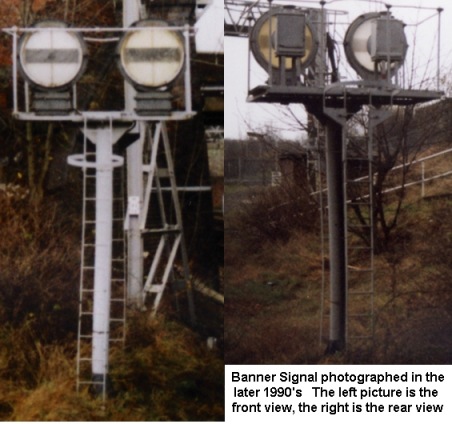
A photograph taken by
John Sullivan of the more modern electric light banner signals will be found in
the section on Signals - Power Operated and Colour Light Types
As
with the earlier disc and bar systems various modifications were introduced to
distinguish differing functions for signals, for example a general practice was
to fit a large X shape to the arms of signals which were temporarily to be
ignored. This practice continues today, colour light signals are covered with a
black plastic bag with a white X of tape over the front.
Shunting
signals were required to control movement within stations and yards, these were
always of the 'home' or 'stop here' type and so that
drivers could identify them they were distinctive in some way. Some companies
used smaller than normal arms, some had very short and fat arms, others had
circle welded on to the arm.
This circle design was generally adopted at
about the time of the First World War to indicate signals that applied to a
goods siding or goods loop. Again there were minor variations: the LSWR had a
white circle added to the standard red and white arm, the LNWR used a black
circle on a standard red arm with a white strips where the circle crossed the
arm, the SECR had a black circle on their standard red arm with a white dot on
the arm itself and the GER and the GWR used a white circle on a plain red
arm.
The GWR had used a large letter S on the arm before this, the S arm
was subsequently used mounted separately lower down the post on a standard
'home' signal as a 'shunt ahead' signal. If down (clear) it
meant 'you can pass the above 'home' signal at danger but only
for shunting purposes'. Several companies appear to have adopted
variations on this S marked arm for this purpose.
You will occasionally
see very small signal arms, sometimes with holes in them, these are usually
'calling on' arms. They were used to allow a train to enter a section
already occupied by another train, the driver being responsible for avoiding a
collision. These were not common, one application was at long platforms where
two passenger trains might be accommodated at one time.
Fig___
Distinctive Signal Arms
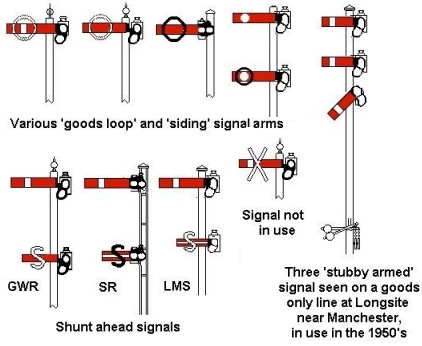
Distinctive signal arms, with the stubby arms, circles, etc.
were abolished in 1948, but those in place remained in use for many years (as
late as the mid 1980's in some locations).
Detonators
In 1845 the
'detonator' appeared, a small explosive charge that could be clipped
to the rail, the weight of the locomotive wheel caused the charge to explode
and the loud but harmless bang could be heard by the crew. Even today every
engine cab carries 10 detonators. They are used for emergency protection, in
the event of an accident the train crew place the detonators on the line to
warn approaching trains. They are also used for assistance protection, where a
train breaks down they are placed on the line to warn other trains of the
obstruction, including the loco coming to assist. Some signals have a
mechanical arm which lowers a detonator onto the track when the signal is at
danger, lifting it clear when the signal is in the all-clear position. This
warns the driver if he or she passes the signal at danger. They are also used
in possessions (when the engineers take on a maintenance job on a section of
track) to warn train crews that there are men working on the track. Another
occasional use for detonators is where a severe temporary speed reduction (TSR)
is in effect. See Signals - Ground and Fixed Signals for details of the signs
used for TSR's.
Signalling in Foggy
Weather
Fog has always been something of a problem for visual
signalling systems and has caused several accidents although the clean air acts
of the 1950's did reduce the frequency and density of fog.
In
foggy weather a plate-layer would be sent out to wait by the signal, placing a
detonator on the track when the signal moved to danger, removing it when the
signal changed to all-clear. The small fog mans hut with a braisier to keep the
man warm close by a signal post was not uncommon. Fleetline offer a small hut
for the fog man and a braiser to keep him warm (N74), these were a common sight
adjacent to important signals.
Various mechanical aids for placing
detonators soon appeared, most used some form of swinging arm with the
detonator on the end, they were never terribly successful but some remain in
use today.
^
Go to top of page
International Good Guys ~ Doing things
properly since 1971 ~ Site maintained by 
All material Copyright © Mike
Smith 2003 unless otherwise credited