Signal Boxes
Most
points and signals are these days operated by electrical and
hydraulic mechanisms, requiring only a small switch or button in the
signal box to operate them. Originally they were operated manually
using a waist high lever connected by rods or wires to the point or
signal involved.
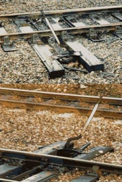
The bottom end of the scale would be a single
lever mounted close by a point in a goods yard, marshalling yard or
industrial location such as a docks area. The lever itself stands
some four feet high (there is a photograph of a shunter standing next
to such a lever in Fig___ above) and they were usually aligned with
the track. These levers were usually mounted on a pair of extra-long
sleepers on the point to be operated. The lever itself sits on a
frame bolted to these sleepers over a small pit with wooden boards
covering the 'works' underneath.
Fig___
Photographs of simple point levers
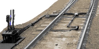
Where the point in question had to be mechanically locked because it was a 'facing point' on a passenger carrying line a second lever was added to operate the lock. Normally these locked points were operated from a signal box but local control as shown below could be seen on minor branch lines and inside passenger stations. Usually there was a protective cover over the mechanism, typically a wooden or metal bridge with sloping ends at either end.
Fig___
Photograph of a local point lever with associated point locking lever
Standard levers were used, some with a straight
lever, others with a bend in the lower end as shown in the photograph
above and the sketch below. These levers were usually (but not always) painted white.
There were alternative designs, some used a short arm with a heavy
circular weight attached which was lifted up and dropped down the far
side. The mechanism and lever on this type were usually black
although the weight was often painted white and the arrangement was
usually aligned parallel to the tracks.
In locations where
only a few points were involved and no signals were operated a
'ground frame' consisting of a set of levers would be
provided. As there were several sets of rods or wires to be taken
from the levers they were usually mounted on a small raised wooden
platform. These platforms often had a light tubular metal 'handrail'
arranged round them. Any of these open air levers which affected a
running line were padlocked in position.
Very small boxes were
sometimes provided for local control, for example at country
stations. These might resemble the upper section of a standard signal
box mounted on a low plinth on the passenger station platform or they
could be a simple wooden hut close by the track. The Prototype range
of card buildings has a small hut type in the set of GWR station
buildings.
Fig___ Local point lever, ground frame and small
signal box
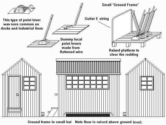
The
covered wooden frame at the front of the hut was where the point
rodding and signal control wires (discussed below) emerged. There would normally be
something similar at the base of a full sized signal box although with rather more wires and rods coming out of it.
There are however several problems with this simple arrangment, for a start there is nowhere to put any kind of log book (signalmen on running lines were requred to log all train movements) and there was nowhere to put any kind of signalling device out of the weather. The simple solution was to add a simple hut over the lever frame, however once communictions such as single stroke bells became involved these were classed as signal boxes and usually marked as such.
Where the box was platform mounted they were usually quite large, nearly as big as a free standing box. In the face of the platform in line with the box would be a large hole where the point rodding and signal wires emerged.
To prevent someone setting (for example) the points into a siding but leaving the signals on the main line indicating all clear a system of 'mechanical interlocking' was developed. At the most basic level this could be implemented by routing the control for the signal through the operating gear of the associated points, so that the signal could not be set unless the points had been moved.
Fig___ Mechanical ground signal with simple mechanical interlocking
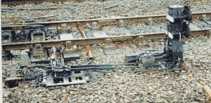
These would only be associated with very simple branch line stations or with goods yards, where (typically) a full height box complete with ground floor locking room handling the main line aspects. At Hale station there was such a box for operating the points in the goods yard as these could not be seen clearly from the signal box at the other end of the station.
This simple approach did not meet all the requirements of a vastly complex railway system however and it soon became standard practice to add a large mechanical arrangement called a 'locking frame' underneath the operating levers of the 'lever frame', leading to the classic two storey design for signal boxes (which also raised the operating position and improved visibility.
If the tracks being controlled were simple, as on many branch lines, the mechancial interlocking of points and signals could be simplified, requiring a smaller locking frame and a shorter building to house them. In some cases the signal box was sited on the station platform with only a couple of steps leading up to the door, although the box itself would extend down through the platform to provide space for the locking room, and the controlling wires and rods would emerge from a hole in the base of the platform.
Where the interlocking was truly minimal a small lever frame could be mounted on the platform itself, however this would have a building round it to protect any instruments and to keep the general public at bay. There are several examples of these very small platform mounted 'signal boxes' on the single track lines in Scotland.
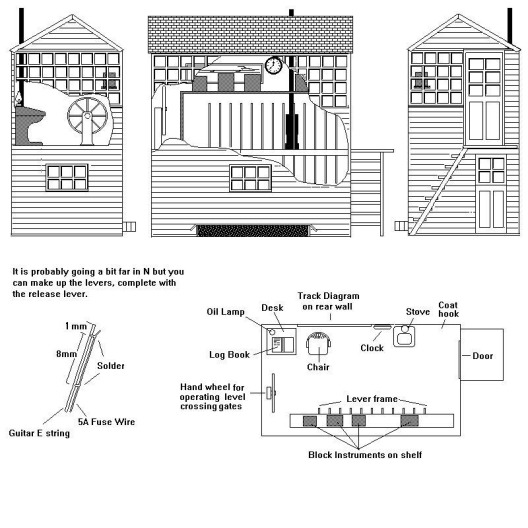
Signal boxes were usually two-story buildings, the upper floor having large windows and containing the levers,
instruments and what have you, the ground floor containing the complex mechanical interlocking mechanisms that prevented accidental setting of points and signals in dangerous configurations. This lower section usually had only a small window or two.
The
British favoured standard designs when building signal boxes proper, this is logical as the ground floor locking frame and upper floor lever frame were built from standard parts requiring standard fittings. You can buy accurate models of standard company signal boxes,
ScaleLink offer GWR and MR/LMS designs in etched metal, but you can
always assume the box is on an 'absorbed' line and built to
the original company specification. During the Second
World War some signal boxes had an exterior cladding of brick added
to protect the lower section, with all the complex mechanical
equipment, from bomb damage.
The large windows in a signal box
meant that the inside is quite visible on a model and some attempt at
filling this void is worth the effort. You can buy commercial
detailing kits for signal box interiors, and these do result in a
beautiful model, but for those of us with less cash it is worth
having a go with materials to hand.
Inside the signal box
there were various electrical signalling instruments, the operational
details of which need not concern the modeller. These were usually
arranged on a shelf above the signal and point operating levers along
the 'front' of the box. This restricted the view from the
front windows but this view was of little value to the signalman, who
was more interested in seeing the train clear of the points to either
side of the box and checking the light was present on the rear of the
train (indicating it was complete and had not left any wagons behind
on the line). These instruments were quite visible and when modelling
a signal box it is worth adding the shelf and the instruments
arranged along it. The instruments were typically about a foot high,
nine inches wide and six inches deep and were mounted in polished
wooden cases. The levers in the signal box were colour coded, the rules were fairly standard and when BR took over they adopted the most common colour codes - black levers for points, blue levers for locking (I believe that applies to interlocks and also to point locks), red levers for home signals and yellow for distant signals. There were also green levers (I believe these were for route indicators) and white levers in some boxes but I am unsure what these were for (possibly calling-on or other special signals).
Fig___ Typical Signal Box Interior
Fittings
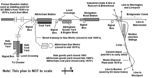
Where there were many points and signals the boxes needed to be bigger, at large stations and complex junctions there might be several boxes located close together. Visibility was also an issue here, quite a number of stations had more than one signal box, each one sighted to offer a decent view of the controlled lines, for example at Altrincham on the Manchester to Chester line there was a large signal box by the level crossings at one end controlling the terminus part of the station and the approach from Manchester and a rather smaller box at the opposite end controlling access to that end of the coal yard and the signals for the line to Chester. These boxes at Altrincham were closed when the line to Manchester was converted to
the new Super Tram system and the British Railways lines changed to
automatic colour light signalling controlled from a signal box at the former junction (Deansgate Junction, near Skelton Junction) where the railway and tram lines diverge.
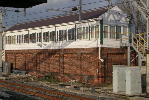
In 1999 Stockport (a junction
station on the Manchester to London line) still has a two large boxes controlling three diverging double-track lines at the London end and a large box controlling the four-track main line to Manchester at the
other. The photo below shows Stockport No.2 box controlling the four-track Manchester line, the largest of three broadly similar boxes controlling this complicated junction station.
Fig___ Large mechanical box at Stockport.
As well as standard and shorter signal boxes there were a few rather tall examples, usually these were set up to provide a clear view of the line, perhaps over an adjacent bridge. These were very much the exception rather than the rule however as they involved making specialised parts for the mechanical linkages, which with the additional building work added to the cost.
Having the lever frame mounted actually above the tracks provided better visibility, in the days before interlocking became standard the signals themselves could be mounted on the roof of such a box but this approach cost more to build and was only associated with larger stations. Once the locking frame became standard this approach fell from favour, although examples have continued in use until very recently and a few may still be operating at the end of the 20th century. Prior to its major rebuilding after the Second World War there was at least one such box on the south approach to Manchester Picadilly station (it was still called London Road Station back then). This was replaced by a modern box located beside the tracks, the photo below shows both ends of this large building which is a typical 1960s style of building.
Fig___ Post war signal box at Manchester Picadilly
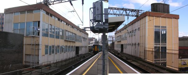
The Hudersfield No.1 signal box was built over the tracks within the station itself, extending from the main station building on one side and supporrted on a platform mounted pier at the other. From a modelling perspective the over the track box saves some space and suggests a large and important station but can get in the way when derailments ocur. The Hudersfield design makes it more difficult to access the couplings when shunting coaches into the station, although not a problem if its a through station with no loco or stock changes required.
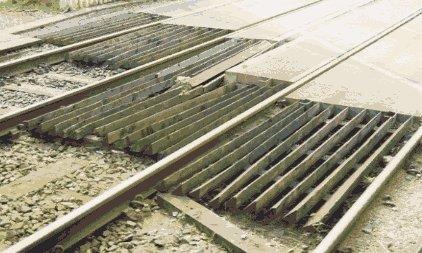
Point rodding and signal wires
One final detail is the point rodding and signal control
wires both of which were black. Points were usually operated by
rodding made originally from steel pipe and more recently from a
channel section with the open side at the bottom., supported in small
frames mounted on short supports every few feet. These are quite
noticeable on the real railway and some attempt at portraying them on
a model is worth the effort. In N the supports can be represented
quite well with short lengths of wire, sticking up about 1mm above
the ground level at about 15 mm intervals. The rodding can then be
represented by stretching and gluing fine thread a long the tops. Rod
operated points could be up to 350 yards away, for greater distance
pull-wires were used, these were not very common in practice but
enabled operation of points up to perhaps 600 yards away. Power
operation means that points can be several miles away but this was relatively
rare before the Second World War.
Mechanical signals are
operated by wires and as already noted these could be anything up to
half a mile away from the signal box. The wires used were generally
quite thin, perhaps 3 mm and can safely be ignored in N as they would
be virtually invisible.
Where the wires or rodding had to cross the underneath a track this was done at right angles.
There were various experiments in using alternative control systems for operating signals, John Webb noted that -
There were many schemes in the 20th Century (Crewe, Hull, LSWR in the Southampton area, Southern Railway after 1923, East coast mainline around Thirsk etc) where some form of power signalling was in use. They included electrical solenoids, electro-pnumatic, electric motor etc. I warmly recommend "Two Centuries of Signalling History" by Geoffery Kitchenside and Alan Williams, published by OPC in 1998 for a quite detailed and well-illustrated tour of signalling developments.
The electrical control of signals and
points means that the wires and rods are replaced by cables. The cables were originally strung on hooks mounted on posts or attached to the walls of cuttings and tunnels but by the 1960s they were usually
laid in the white rectangular trunking alongside the track (see
Fig___). Where the cables pass under the rails it is usual to run them
through a length of tubing, from the 1980s this was usualy about two inches in diameter and coloured
orange.
As noted above the longer term plan is to replace the
signal boxes with centralised computer controlled network control
points but for the moment at least there are still plenty of the old
manual signal boxes in operation and these are unlikely to disappear
before the end of the first decade of the twenty first century.
Signal Box Spacing
From looking at maps I
would suggest signal boxes should be something like three or three
and a half miles apart, some were separated by as much as much as
five miles (obviously with no points or signals in the centre of the section between the boxes, see above) but some were relatively close together. On my local
Manchester to Chester line the distance between the two signal boxes
in Altrincham and the smaller boxes to either side at Hale and
Navigation Road was well under a mile.
Fig___
Altrincham and its adjoining stations
John Webb, who has considerably more knowledge of signalling than I do, pointed out that . .
Regarding your comments on the spacing of signal boxes. There were two major factors -
(a) Limits by the Board of Trade on the distance over which manually operated points could be worked, finally set at 350yards
(b) The complexity or lack of junctions in the area and the quantity of traffic. The former would require more boxes where junctions were close together; the latter might, for instance at a large station, require two or more boxes to operate the signals just to divide the work-load up to minimise potential delays.
Another factor affecting the spacing of signal boxes was the introduction of the 'Intermediate Block Signals' system. This used electrically operated semaphore or colour-light signals together with track circuits worked from a distant signal box. This system was used to either divide up long sections of track so that more traffic could be handled, or to replace 'break-block' signal boxes put in with the same intention but possibly difficult to man reliablely.
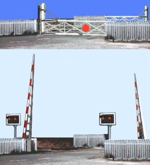
Level Crossings
The
Railway Clauses Act of 1845 introduced the law that all railway
property must be adequately fenced off from the public. Several early
railways had already started fencing off their property to avoid
accidents and the Liverpool and Manchester railway even had gated
level crossings on its line, each attended by a company 'policeman'.
The gates were normally closed to road traffic and opened by the
policeman as required. The practice of having the road normally open
and the railway line blocked by the gates started in the latter part
of the 19th century, when the electric telegraph was introduced
enabling gate keepers to be advised of an approaching train. Level crossings were usually equipped with some dregree of street lighting, usually this was provided by the railway company although the lights themselves might be conventional street lights mounted outside the gates on the pavements. The Ratio 'platform gas lights' serve well enough as the kind of lighting often provided. It is perhaps worth noting that at some crossings, at least in country areas where there was no street lighting as such, the side facing up the road was fitted with a red glass, providing a warning to road users, the other three sides being plain glass to illuminate the crossing itself. This was not universal, in built up areas all the faces of the lanterns were plain glass, such as the post mounted lights at Hale illustrated below
On
quiet lines the gates were operated by hand, a man would walk one
gate shut then the other, in these situations there were usually only
two gates used. The gates on busy lines were operated by a mechanical
linkage operated from an adjacent signal box. There was a large
wheel, mounted at the end of the box closest to the crossing (see
Fig___), this meant the signal man did not need to leave his box to
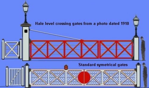
operate the crossing. The upper drawing in the sketch below shows the asymetric set of gates at Hale on the CLC as they were in about 1910, when I remember them they had been painted white and a red 'bullseye' added to the longer gate (this ended up in the centre of the crossing when the gates were closed, see Appendix 5 for a sketch). The lower drawing shows a 'typical' set of symetrical gates. The gate to the side, allowing pedestrians to cross the line, was linked to the main gates on the roadway, those I remember locked shut when the main gates were closed. As I remember it women with prams and the like had to use the roadway to avoid this gate.
Fig___ Level Crossing Gates
If a signal box was not conveniently sited a
small house was often provided for a 'crossing keeper'
who's job it was to open and close the gates, these gates would
be operated by hand rather than by mechanical linkage. On quiet rural
lines the train crew often had to operate the gates when they reached
them and this system was still in use on at least one rural line in
the North East as recently as the late 1980's.
The road
surface on the crossing was built-up to rail height so that vehicles
could cross the tracks, where the gates were operated by a wheel in
the signal box the surface of the crossing was made up of timber to
allow access to the 'works' underneath. At crossings where
the gates were operated by hand the surface of the road might be
standard macadam or later tarmac. It was common practice to add
timber baulks just inside and outside the rails on these latter
crossings to reduce the sideways pressure of road-vehicle wheels on
the rail and ease repairs to the track.
When the Light
Railways Act was passed in 1895 the newly designated light railways
were allowed to do away with gates at their level crossings. The
Weston, Clevedon and Portishead Railway became a Light Railway in the
late 1890's and they actually used the level crossings as halts.
The company had bought some American looking coaches (originally
built for export to South America), which had open platforms with
steps at each end. These were operated in pairs and the train was
stopped with the centre pair of platforms on the level crossing for
people to get on and off.
One problem with un-gated crossings
was that cattle being herded along the road could wander off up the
railway track. To avoid this it was standard practice to add a set of
triangular wooden beams called a 'cattle grid' across the
track. The cattle could not walk over these grids (humans often have
trouble with them as well). Where a farm access road crossed the line
and the lay of the land allowed it was normal to arrange a bridge or
a short tunnel (called a 'cattle creep') to allow the
animals to be moved from one side to the other. Where the crossing
was on the flat there would usually be gates in the fence to allow
cattle to be herded across the line (usually referred to as an
'occupation crossing'), but these would be arranged to open
away from the track so if left open they would not be a hazard.
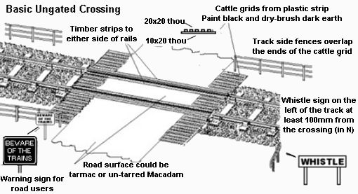
At un-gated crossings there would
normally be a sign to warn road users and the railway line would have
'whistle' signs on the approaches to the crossings.
The sketch below shows such a crossing, as shown this would serve for layouts from the 1920s to about the 1970s. After that date modern signage would be expected and warning traffic lights would be present (usually with the emergency telephone on the post supporting the lights).
Fig___ Level
Crossing
As traffic increased in the 1930's accidents at un-gated crossings
became an increasing concern, one option (used on the Weston,
Clevedon & Portishead Light Railway among others) was to fit
traffic lights operated by a pressure switch on the railway
track.
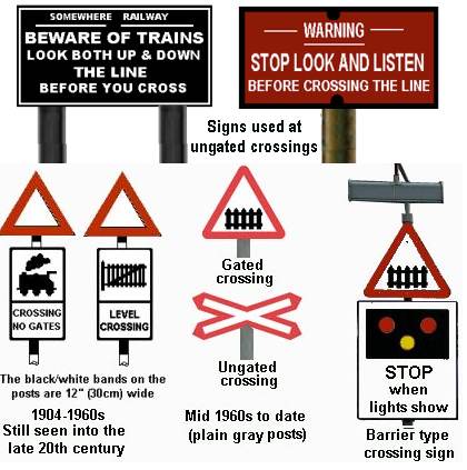
All level crossings, gated or open, would have a standard cast metal warning sign set on a post on the approach road. From the 1904 both gated and ungated types had a distictive cast metal warning sign with an open centre red triangle on top (as shown below bottom left) set some distance (typically 100yds or so) from the crossing. The sign changed in the mid 1960s (along with all other road signs), although in more rural locations the old signs lasted a for a very long time. With the introduction of the lifting barrier type, all of which are considered 'gated' even if they have only half barriers, an additional notice was added to the sign as shown in the sketch below.
Fig___ Level Crossing Warning Signs
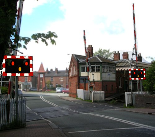
The first lifting barrier type level crossing in the UK (based on a French design) was set up
near Uttoxeter on the Churnet Valley line in 1961. As these lifting barriers to not block the railway line
these crossings require cattle grids to either side to prevent stray
animals walking up the line.
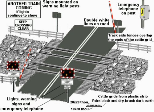
The lifting barriers can be operated by a signal box (located some distance away but watching the crossing via CCTV camera) or they can be automatic. The automatic lifting barrier crossings use half-barriers which only
block the left hand lane of the approaching road, leaving the exit
from the crossing clear. The lifting barrier crossings are equipped with a pair of red light (flashing alternately) above an abmer warning light. They usually have a siren of some form that operates when the amber light is showing, prior to the barriers lowering. At my local crossing the lifting barrier was fitted with a bell, whoich was changed for a siren following complaints that people in the local pubs thought the bell indicated 'last orders' (this was when pub opening times were restricted by law and a bell was rung to advise people they had five minutes to order and drink).
The automatic half-barrier type is fully
automatic with the gate motors controlled from the track circuits
supplemented by wheel operated treadles to give more accurate timing. A sign is usually placed on the pole supporting the flashing lights, warning people that if the barriers stay down then another train is comming (to discourage people from 'weaving through' the barriers). Also on this pole is an emergency telephone to contact the signal box for the section in an emergency. There are usually double white lines down the centre of the road for some distance either side of the crossing, indicating 'no overtaking' to prevent people doing so and finding themselves on the crossing. In the example shown below the detail was taken from a photogaph, the white lines had evidently been recently repainted as they do not usually extend across the rubber decking of the crossing itself (where road marking are painted on to these it is not unusual to see the blocks put back in a different order, leaving elements of the markings in some rather odd places).
Fig___ Typical automatic 'half barrier' level crossing
Note that, up to the 1950's,
the track at a level crossing with swinging gates usually had a
timber inflill between the rails so that the 'works'
underneath could be serviced. Where lifting barriers were employed
the timber infill was replaced by pre-cast concrete slabs set into
steel frames and by the late 1990's this had been replaced by
pre-formed rubber blocks with a tread pattern moulded onto the top
surface.
Fig___ Photo of cattle grid and concrete
in-fill
There has been considerable debate regarding the
delay required between the barriers coming down and the train
arriving at the crossing especially where 'half barriers'
are used. If the delay is too long there is a danger that motorists
will try to drive round the barriers, too short a delay and slow
moving vehicles might not get clear of the crossing in time. In 1968
a 120 ton transformer being moved by road was hit by a train at one
of the new automatic half barrier level crossings. The tractor units
pushing and pulling the loaded road trailer could only travel at a
couple of miles an hour and the transformer was already on the
crossing when the barriers came down. The crew of the lorry, and
their police escort, failed to use the track side telephone to check
with the railway staff in spite of a large sign instructing them to
do so when transporting an abnormal load.
There is a story,
probably apocryphal, that in certain parts of the country they had to
change the wording on the warning signs for motorists. The story goes
that the original wording was 'Wait while lights are flashing',
but British Railways forgot that in some dialects the word 'while'
means 'until' and a farmer complained to his local station
that he had waited nearly an hour for the lights to start flashing
then had to pull off the crossing very fast as the barrier started to
descend.
On narrow roads a single gate was often used, these could be operated by a mechanism in an adjacent signal box, by a crossing keeper walking each gate in turn or (in remote areas) by the train crew. The example shown below was close by a small station on a double tracked line and was (I elieve) hand operated as there was no signal box close by. Where the road was narrow and the railway line was single track the gate itself could be quite small, but that is still twice as wide as a typical farm gate. Single gate crossings were used on minor roads, more so in the country than the town. These single gate crossings could be replaced by a single lifting barrier, either a 'half barrier' across one lane of the road or (as shown here) a full barrier that extends right across the road.
Fig___ Single gate and single barrier crossing
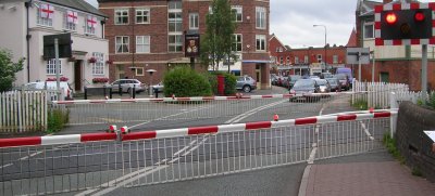
At busy crossings and in built up areas it is normal
to install two pairs of lifting barriers which form a complete
barrier across the road. As these block the road and might trap an
unwary motorist or pedestrian they are usually remotely operated from
a signal box or control centre. These are usually some distance away
and at my local station there is a tall post mounted next to the
track with a pair of TV cameras to allow the signalman to see the
crossing. When open there is no barrier across the railway so again
cattle grids are required to either side of the crossing. The example shown below is the current double-barrier set at Hale, south of Manchester. Sketches showing the earler swinging gates used at this location in 1910 and in the 1960s can be seen in Appendix 5 - Hale Station.
Fig___ Double barrier crossing
When the barriers reach across the whole road they normally have a 'skirt' of metal rods suspended below them to stop children and dogs running under the barrier getting onto the line. When the barriers are raised these fold back under gravity to lie close to the barrier and are difficult to see.
Fig___ Drop-down 'skirt' on barrier crossing
Replacing the older gated crossings has proved a long slow business and even at
the end of the 1980's there were still a lot of the old manually
operated swinging gate crossings in use. In places where road and/or
rail traffic was high British Rail and local corporations and
councils have worked together building road over-bridges to eliminate
the level crossing entirely.
By the mid 1990's there were
over four hundred half-barrier crossings in use and about three
hundred full-barrier remote controlled crossings. In more remote
locations no barriers are used but a set of warning lights is
provided. At locations where crossing may be occupied for some time
(for example cattle may be herded across the line) a telephone is
provided, linked to the local signal box or control centre, so people
can check the line will remain clear. There are nearly a thousand of
these un-gated crossings equipped with lights and a telephone but
there are another four and a half thousand un-gated crossings on the
system with only a warning sign. Most of these are in built up
industrial areas, docks and the like.
The 1845 Act required all railway company property to
be safely fenced off but this did not apply to private sidings. In
dock areas and large industrial estates there were often railway
lines crossing roads with no gates, lights or other mechanical aids.
There would be a sign (usually BEWARE TRAINS CROSSING) and the
railway or industrial staff would provide a man with a red flag to
stop the traffic when a train was crossing. This man would ride on
the front steps of the loco which was usually travelling slowly in
these areas.
Similarly where a siding from the railway crossed
a road in to a factory the normal practice was to have a gate across
the railway access and another across the entrance to the factory but
the track between was often unprotected. My local town gas works in Altrincham was
some distance from the railway station but was connected by a line
laid in the middle of the road from the railway coal yard to the
works. There was a gate across the entrance to the railway yard with
another at the gas works and the rakes of coal, coke and tar wagons
were hauled up the road by gas company locomotives. They had a small
steam railway saddle tank engine and an unreliable diesel shunting loco but the
job was often done by a steam road lorry also owned by the works.
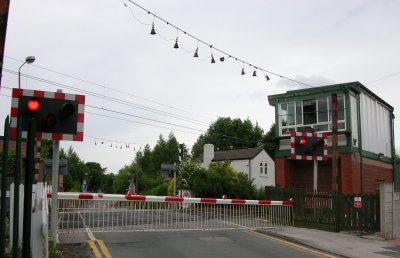
One oddity on the Altrincham line is at Deansgate Junction signal box (which controls the diverging line to Skelton Junction and now operates the signals on the Chester line through Altrincham and Hale), in the 1930s when the line was electrified there was quite a lot of industry in the area, hence a number of large lorries with even larger loads were expected to use the level crossing. To prevent people hitting the wires the simple expedient adopted was to run a cable across the road on each side from which were suspended a number of cow bells. Non of the other level corssings on the line have had these (at least since the later 1960s) and to date I have traced no formal explanation or other location equipped with these bells.
Fig___ Cow bells still in place at a barrier crossing in 2007
^
Go to top of page
International Good Guys ~ Seeking the Truth since 1971 ~ Site maintained by

All material Copyright © Mike Smith 2003 unless otherwise credited