Telegraph
Poles, Cable Conduits and Switch Boxes
To carry the telegraph and telephone signals and electrical block instrument signals the railways had to run wires alongside the track. Prior to the second world war electrical wires had to be
insulated using natural rubber or material such as gutta percha, both of which
degraded over time, hence it was more economical to suspend telephone and
telegraph wires from glass or ceramic insulators on the lineside telegraph
poles. Gutta Percha is a rubber-like Malayan gum obtained from trees which is liquid when heated and solid when cool. It is an excellent insulator and was used as the main cable insulation for underground and under sea cables for many years.
This topic came up on the uk.railway newsgroup so I asked if the system used an earth return (requiring a single wire) or a pair of wires to get an idea of how many wires would be appropriate for a branch line. The reply from one of the regulars on the group answers both questions rather well
- Do block instruments and single stroke bells use earth
- return (requiring only one wire) or do they all require
- a pair of wires? I was wondering how many wires would
- run alongside a 'typical' branch line.
Originally *everything* used Earth return (later many places had a
metallic common return, still used in some places). Typical Block rig
was Up Block, Down Block, Bell.
Signal arm and light repeaters also
used Earth return.
Telegraph pole routes typically used 200lb (per
mile) copper wire, more for mechanical strength than conductivity, so
as can be imagined this was rather costly to begin with, and providing
individual returns would have doubled this.
By contrast, modern
railway telecomms cables (which we signalling types sometimes use for
our stuff as well) have cores of 20lb, 88 ohms per loop mile (just one
of those values imprinted on my brain from years back !).
When metallic returns (line wires or cable cores) started to be used,
block and bell often had their own, so you would have Up Block, Down
Block, Block Ret, Bell, Bell Ret.
Note that the bell circuit works in
both directions over one wire. At each end, the Tapper key Normal
(released) connects the line to the bell, and the battery + there is
disconnected, and when pressed, disconnects the bell and puts the
battery + to line, ringing the bell at the other end. If the keys at
both ends are depressed together, both batteries' + are put to line
and just oppose each other, though some current will flow if they are
of different voltages.
Using E or common return can cause some interesting effects if it gets
disconnected somewhere, as the current can find another path back to
the battery via some other equipment, which may than operate
unexpectedly. Many, many years ago, I was tracing wires in an old
cable cupboard on the end wall of the signal box, prior to it being
replaced, when the signalman called down "What the ____ have you done
?!". He had pegged LC on one block instrument, and all four needles
(two pegger and two non-pegger for two pairs of running lines) in one
direction were showing partial "Line Clear". Somewhere in the cable
cupboard, a return connection had gone high resistance, but
electricity is funny stuff and it had found another way 'home',
backwards and forwards between the two signal boxes through all needles
in series.
These days we usually have plenty of cable cores available to us, the
major cost is in the route (troughing, direct burial etc), the cost
difference between 27 & 37c signalling, or 20 and 30 pr tele cable is
tiny compared to the cost of actually installing the cable (of any
size), so the preference is for separate metallic returns for all
circuits.
Wobbly Bob
From which it would appear that the average branch line should have five or seven (including telephone) wires running along beside the track. On main lines
there would be several pairs, trunk routes often had upwards of thirty pairs of
wires running along beside the track. The rhythmic dipping of the suspended
wires seen through the window was rather hypnotic and formed an enduring memory
of train travel up to the 1970's. At one time the railway leased spare capacity
on these lines to the General Post Office (British Telecom was only separated
from the Post Office in 1984) for their telephone and telegraph
traffic.
There are plenty of commercial sources of telegraph poles, the
softer plastic type are less susceptible to damage. These can be 'strung' with
fine mono-filament fishing line but this has no 'dip' between the poles. With care
5 Amp. fuse wire can be used but this in turn is much more liable to accidental
damage when the Big Hand from the Sky reaches in to retrieve a derailed wagon
or clean the track.
Following the war, during which new insulating materials such as
polythene were developed (polythene had been invented in by R.O. Gibson working for ICI at Winnington in Cheshire in 1933 but was not adopted for electrical insulation for several years), it became cost effective to replace the bare wires
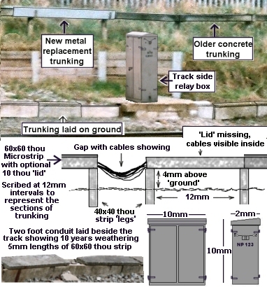
suspended from telegraph poles with insulated cables. Where these cables are
run in the open, with no convenient wall to mount the clips on, they are
carried in a white concrete rectangular tube run along the line side. This
conduiting was a standard size, roughly six inches wide by nine inches deep and
came in standard lengths. In some locations more than one was required to carry
all the cables. These conduits were initially supported about every four feet
on a concrete pillar and occasional sections would be broken or missing,
revealing a group of wires sagging down. Metal clips were used to hold the
'lid' on the top, although this also was often missing. The metal clips
tarnished over the years to quite a dark brown colour. Where the conduit ran
along platforms and the like it was laid on the ground, often half buried in
the ballast beside the track and by the 1980's the standard practice seems to
have been to run all the conduiting along the ground. More recently (since
about 2003) there seems to have been a shift to using metal conduiting, roughly
the same size as the old concrete type but much thinner walled and lacking the
cover or top.
Fig___ Cable conduits
The telegraph poles were
gradually replaced by these conduited cables and had largely disappeared by the
early 1980's.
Heavy power cables for use on the electrified lines and
power cables feeding electric signals and points were often suspended from
abutment walls and the like using U shaped metal clips. The cables were
generally rather dark grey in colour and about two inches (5cm) in
diameter.
Electric point control, point heating (for winter) and
electric light signalling systems all require track side relay boxes and since
the 1950's these have been fairly standard, an example is shown in the picture
above. These track-side electrical boxes are usually painted light grey and,
when positioned between the tracks, they sometimes stand on short legs to raise
them above the ground. You will see a lot of these on the modern railway, for
example a single point at a remote single track junction would typically have
three; one for the point motor control, one for the point heating circuits
(used in winter) and a third for the local 'track circuits'. Models
of these boxes are available commercially (Langley offer a pack of three in
white metal) but they are not difficult to scratch build.
One side
effect of the change to digital control system is a reduction in the size of
the relay boxes beside the tracks. The new boxes are small and T shaped,
standing only about two feet high. As with the older relay boxes they stand on
a concrete platform, set back slightly from the track.
Fig___ Modern
solid state relay box
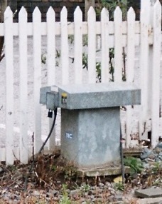
This single small box replaced two of the older type
illustrated above.
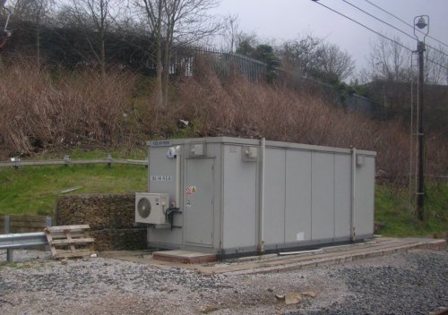
There are also larger installations, the example shown below is at Stockport and forms part of the track redsign and resigalling in about 2005. The photo was taken in 2007. Note the air conditioning unit mounted low down at the end, also note the elderly 'yard lamp' still in position and possibly in use.
Fig___ Modern signalling system, portable switch room.
^
Go to top of page
International Good Guys ~ Blunting the
cutting edge since 1971 ~ Site maintained by

All material Copyright © Mike
Smith 2003 unless otherwise credited