In practice you can get away with relatively few signals on a layout, which is a help if you want the things to work. For sidings and the like non-working ground disc signals can be used, these coexisted with electric colour light signals in some locations until the late 1990's and look like remaining in use for many years yet.
Note that the distance between the 'Home' signal protecting the entrance to the station and the 'Starter' signal controlling the departure end must be at least as great as the longest train that will use the line, usually a little more. Hence, even if your station is a small halt on a branch line with a two coach platform, the signals for the arrival and departure end of any platform must be as far apart as at any normal sized station on the same line. A common mistake seen on layouts it to have these signals much too close together.
Electric and electro-hydraulic semaphore signals were not common on the railways prior to the 1980's. Mechanical signals require a signal box and if a level crossing was required then a logical move was to place the signal box there, so the signalman could operate the crossing gates as well as the local signals. It would be unusual to see a gated level crossing without a signal box next to it but in some locations they had a small cottage for a 'crossing keeper'. If the road crossing the railway was at all busy the crossings with only a keepers cottage were often eventually replaced by a road bridge, often quite a hump-backed affair.
Colour light signals, which means the later 1970's in most locations, do not require a signal box but you may still see an disused empty box next to a lifting barrier type level crossing. To date I have not seen any signal boxes converted for commercial use, although of course many station buildings are now used as offices and the like.
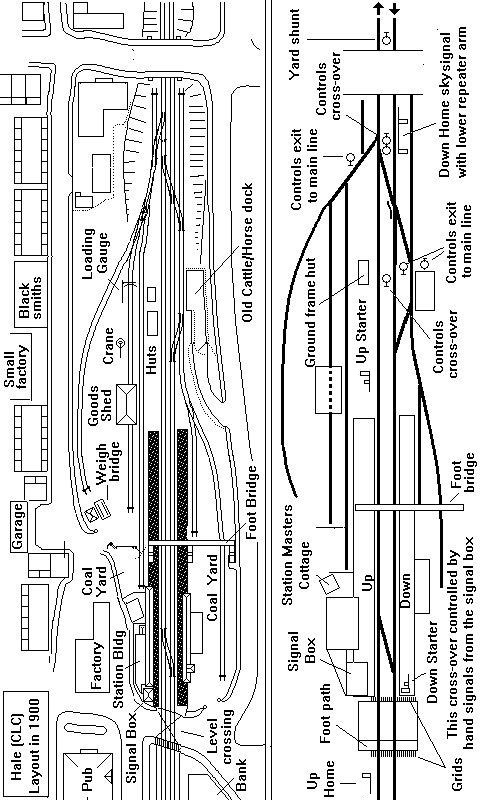
To illustrate the basics of prototype goods signalling a simple example is probably the best bet and once again a layout based on that at Hale on the Manchester to Chester line will serve well.
There were 'home' and 'starter' signals controlling the entrance and exit from the two platform lines, one of the home signals was a tall 'sky signal' located close by a road over-bridge. The signalman could not see the goods yard from his box so there was a separate small signal box or 'ground frame hut' which controlled the various ground signals for controlling these lines as well as the points in the yard area and the two cross-overs used for shunting.
I have shown secondary 'shunt ahead' arms on the starter signals as the Chester end signal is a bit close to the crossing and the Manchester end starter is before the goods yard access. I do not know if the original signals carried these additional arms but the one on the Up line starter seems likely to have been required.
Fig___ Signalling for a typical double track small station
If dealing with a single track line the basic principles remain the same but with a few minor detail changes such as the 'tablet exchange' apparatus for single line working.
Real railways tended to be long and thin, for example platforms might be placed to either side of a road overbridge, and the goods facilities were typically along the line at one end of the station rather than alongside the passenger station. Stations with the platforms and goods facilities arranged to either side of the line did exist however and the example shown has been drawn to illustrate as many features as possible in a single example. The signalling is perhaps a bit comprehensive for such a small station on a single track branch line but it would not be unreasonable if the branch was busy.
Fig___ Typical single track station with passing loop and bay for subsidiary branch passenger trains
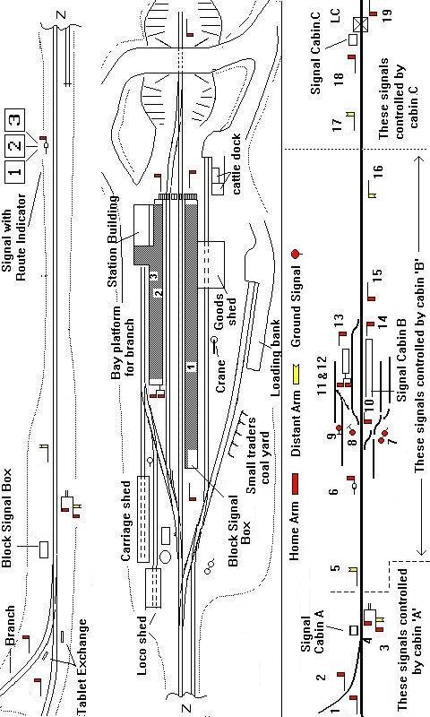
In the example shown the signal box at the junction ( A) controls traffic to and from the branch and has tablet exchange equipment for both the main and branch lines.
The signal box on station platform (B) is the block controlling box for this section and the tablets would be exchanged by staff on the platforms. This signal box controls the signals on the approach to and inside the station. The signal box shown on the right of the small track plan at the bottom (C) would not be equipped with tablet exchange, there is no 'loop' on the section it controls to allow trains to pass.
In practice, if a bridge could not be built over the line this might have been a simple set of hinged gates with a crossing keepers cottage beside it rather than a full signal box.
Signals controlled by Box A.