Track
Circuits, Warning Systems and Industrial Signalling
Track
Circuits
In the late nineteenth century experiments were made
with electrical train detection systems and in 1901 the first practical units
were installed. In these the metal axle of the locomotive completes an
electrical circuit between the two rails and feeds a signal back to the control
box. The electrical signal can automatically operate points and signals, or
change a light on a control panel so the signalman can monitor a train's
progress
The most successful systems used a system patented by an
American engineer by the name of William Robinson in 1872. This system uses an
electrical current passing up one rail then via a relay coil and back down the
other rail. The relay is normally held 'on' by the current but the
train axle short-circuits the two lines causing the relay to drop out. This
system fails safe as if the circuit is broken the relay also drops out and this
technique forms the basis of modern 'track circuiting' train
detection systems.
The individual lengths of rail have to be
electrically bonded as the electrical connection achieved by the fishplates is
unreliable. The bond usually takes the form of stiff wire (No 10 Gauge) which
appear to be welded into holes in the rail. These wires are often passed behind
the fishplate to prevent vandals bending them up onto the top of the rail. At
the end of each length of track forming a single circuit the rails are joined
with white insulating fishplates (he bolts are the standard rust coloured
type). This bonding is less of an issue these days when so much of the track is
of all welded construction.
On electrified lines you will see short
lengths of thick cable (about an inch (25mm) in diameter) across the joints to
provide the electrical return path for the traction current. As with the track
circuiting wires these cables are normally in pairs in case one breaks.
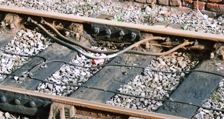
In the photo you can
see the heavy links used for the electric traction return and, if you look
closely you may be able to see the stiff wires used for the track circuit
bonding as well. The black wires clipped to the sleepers are part of a train
detection system, this particular line is now used for trams which use this
variation on the 'wiggly wire' idea.
Track circuits were introduced in the
British railways in the early part of the twentieth century but they only
really became common in the later 1920's. One odd use was on the LNER line
into London in the late 1930's where electric colour light signals were
activated by an approaching train operating a track circuit, the theory being
that as the light was not burning continually it would last longer, the idea
did not catch on however.
Where small and light weight vehicles are used
dirt on the line can prevent the circuit being completed, small shunting
locomotives operating in track circuited areas (notably the British Railways 03
class) often had a wagon permanently coupled to them to ensure that the track
circuit was completed. As the weight of the rolling stock has reduced,
particularly the lightweight Diesel Multiple Units used for short-haul
passenger work, a new problem has evolved due to rotting leaves on the track in
autumn. The thick mess on the rails can effectively insulate the track from the
wheels, preventing the electrical circuit from being completed. This is a
serious and potentially dangerous problem and both British Railways and
Railtrack have funded on-going research into methods of cleaning the track
surface.
Automatic Warning and Train Control
Systems
In 1906 the Great Western Railway developed a system
to sound an alarm in the loco if it passed a signal at danger, this was called
the automatic warning apparatus. This system used a power operated ramp mounted
between the tracks and linked to a nearby signal. When activated the ramp
triggered an audible warning in the drivers cab in case the driver had missed
seeing a distant signal at danger. This was not the first such device but the
GWR design incorporated a signal for 'all clear' which earlier
systems lacked. By 1929 the GWR had developed the system so that it would
automatically apply the brakes if a driver failed to acknowledge the warning.
This improved system was called Automatic Train Control or ATC. The LMS, LNER
and SR did not adopt the system at the time however following a severe accident
on the LNER in 1937 that company did begin work on a system of their own.
Following the nationalisation of the railway system a new version was widely
introduced known as the Automatic Warning System or AWS . This was functionally
identical to the GW ATC system but used a non-contact magnetic system instead
of the electromechanical arrangement, this made it suitable for higher speeds
and reduced the maintenance. The last of the GWR ATC installations was
converted to British Railways standard AWS in 1979. Note that where a track
might have trains passing in either direction (notably in stations) you will
see two AWS ramps placed back-to-back, and example is shown below.
Fig___ Photos of an AWS
Ramp

AWS and ATC
were taken up rather slowly by British Railways, but the UK has generally
lagged behind the rest of Europe in this area. There is an electric locomotive
at the Manchester science museum that was originally used on the DC
'Woodhead route', then sold to the Dutch, who use a lot of DC power
and who added their own safety systems. I was fortunate enough to have these
explained to me in some detail by one of the Museum staff and it was thought
provoking.
When updating this document I posted an enquiry on the
uk.railway newsgroup on this issue. The following was one of the replies:
BR fitted two "experimental" ATP systems - one on the GW main line
between Paddington and Bristol, the other on the Chiltern lines. As far as I am
aware they are both still in use, and if the GW system had been "switched on"
would have prevented the Southall crash. The Channel Tunnel Rail Link has a cab
signalling system with its own ATP based on the signalling used on French high
speed lines.
By the 1990's British Railways began work on an
improved system which they called Automatic Train Protection (ATP), similar in
principle to the GWR's ATC, which would actually stop a train if a driver
passed a signal at red. This became the Train Warning and Protection System
(TWPS). This all happened after I had completed the initial draft of this
document however TWPS and the future European Rail Traffic Management System
are further discussed below.
With the general introduction of colour
light signals following the 1955 modernisation plan things started to change
again with increasing use of automatic controls such as 'track
circuiting' (as discussed above). Increasing use of electronic control
throughout the railway system has meant most of the old manned signal boxes
have been closed down and replaced with automatic 'relay boxes'
containing the circuitry. These are also used to house the control circuits for
electric point heaters, even where the points themselves are operated by
mechanical linkages. See Communications, Control and Signalling - Communications & Control Systems for illustrations of the relay boxes used.
A couple of the modern
electronic signalling control centres can replace as many as two hundred manual
boxes. The points and level crossing of my local station at Hale, some ten
miles south of Manchester, are actually operated from a control centre in the
city centre (Deansgate Junction to be exact).
The early twenty first
century should finally see the end of the old electro-mechanical relays used
for train control and monitoring systems and a switch to fully solid state
circuitry. In the mid 1980's the first microprocessor controlled
interlocked signalling installations were built for British Railways, initially
the system was called 'Solid State Interlocking' or 'SSI'
for short to distinguish it from the electro-mechanical relay systems. The
first installation of SSI was at Leamington Spa on the London Midland Region of
British Railways in 1985, following some four years of joint development by
British Railways, GEC and Westinghouse. Being microprocessor based the system
could make use of 'serial data links' which greatly reduced the
amount of wire running along the track side. The unit directly controls power
to both the colour light signals and 'Clamplock' electric point
motors using all-solid-state circuits with no moving parts.
Following
privatisation Railtrack became the custodian of the railway system but the
British Railways signal building works had already been closed down and outside
contractors were handling the work, the 'big three' in this area
being Adtranz, Alstom and Westinghouse. The maintenance of the signals, which
had been dealt with by BR staff, was contracted out to private companies by
Railtrack but in 2003 the successor to Railtrack, Network Rail, is bringing
this work back in-house. The BR signals design offices were sold off at
privatisation and became independent consultancies.
Railtrack have
spent a lot of money expanding the application of the AWS system and has
developed an improved version of ATC/ATP called the Train Protection Warning
System (TPWS). This adds automatic speed detection and automatic brake
application to the AWS system where a signal is passed at red and I understand
it has been fitted throughout the system. Another new device is the Drivers
Reminder Appliance which sounds a warning in the cab if a train passes a
platform starter signal at danger and includes provision for automatically
applying the brakes if a train passes a signal at danger. I understand that
this device remains uncommon due to cost constraints.
As noted above the
development of TWPS occurred after I had finished the initial draft of the
document. As I understand it the system works by having a receiver linked to a
timer on the locomotive and two low powered transmitting antennas on the track.
The train passes over the first antenna the timer starts running, when it
passes over the second the timer determines if it is going too fast and applies
the brakes, sounding an alarm in the cab. At a signal the two antennas are very
close together, if the signal is at stop and the train is moving TWPS will
activate the brakes.
Fig___ TWPS grids
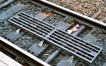
The picture shows two grids placed side by side, as seen on platform roads, crossing these at more than a crawl will activate the on-board warning and braking systems.
A search on the internet for TWPS produced the
following information.
In 1994 a cross-industry project was set up to establish
what could be done to reduce and mitigate signals passed at danger (SPAD). TPWS
was one of the measures put forward in a report by the SPAD reduction and
mitigation (SPADRAM) project in 1995.
TPWS has been designed to be an
enhancement to the Automatic Warning System (AWS), which gives audible and
visual warnings to drivers of almost all signals as they approach and provides
a simple visual reminder of the last signal passed. AWS applies brakes if a
driver fails to acknowledge an audible warning of a signal showing any aspect
other than green, but provided the driver acknowledges the warning the brakes
are not activated. However unlike AWS, TPWS will automatically apply the brakes
of a train travelling too fast to stop at a signal fitted with TPWS equipment
regardless of whether the driver has acknowledged the AWS warnings.
In 1996
a tender was put out to the supply industry outlining the system Railtrack
would like to see developed. Redifon Mel (now Thales Communications) put
forward a system that was accepted and 1996 saw basic equipment developed. 1997
saw further development work culminating in the start of a trial on nine
Thameslink trains and at 20 signals on their routes.
Automatic Warning
System (AWS) will still provide the train driver with an audible warning of the
approach of a signal or sign that must be observed, and tells the driver if the
signal is green.
TPWS will apply an automatic brake application if a train
passes a signal at danger. This is achieved by two loops in the track near the
signal. If the train passes these loops it detects a low radio frequency, which
causes a full emergency brake application to be made for a minimum period of
one minute. The driver can only reset the system after this period and after
seeking guidance from the signaller. The train will therefore be stopped. At
speeds up to about 45 mph the train will be stopped in the built in safety
distance, where there can be no danger of collision (known as an overlap),
beyond the signal (typically 200 yards).
Where the train may approach a
signal at more than 45 mph, or the safety margin is shorter than typical, then
an overspeed sensor will also be provided on the approach to the signal. This
similarly transmits low frequency radio signals to the train if the signal is
red. The train is able to use these radio signals to determine if it is
approaching the red signal at a high speed and thus to apply the brakes before
the signal is actually passed. Again once the brakes are applied the driver is
unable to release them for one minute.
Up to speeds of about 75mph TPWS will
stop a train in the prescribed overlap. Over this speed TPWS will still apply
the brakes, however it may not stop the train within the overlap, but it will
significantly mitigate the effects of an incident. TPWS has been tested and has
been proved to work at speeds up to 125mph. Whether or not a collision would
occur in such circumstances depends on individual cases, for example, the
distance to a potential point of conflict.
The industry has identified
ERTMS as the future for rail safety.
By the mid 1990's Railtrack was a member of the ERTMS working
group. ERTMS will see the end of traditional signal boxes, these will be
replaced by computerised Network Control Centres. Under the ERTMS system the
NCS has a secure digital radio link to the drivers cab (see under
Communications above) allowing data from the control centre to be presented to
the driver whilst the locomotive itself uses passive track side beacons called
'bailses' to keep monitor its speed and its position on the system.
Railtrack is currently (1995) researching a completely new system of
train control called the Train Control System or TCS. This system has been
designed from the beginning to integrate with the European Rail Traffic
Management System (ERTMS), the system already being implemented in the rest of
Europe.
If the British Radiocommunications Agency allocates the
appropriate frequencies Railtrack believed TCS could be installed throughout
the network by 2003 to 2005. TCS includes automatic warning and automatic train
protection (including the automatic application of brakes), it allows
bidirectional running on all lines and will allow the maximum speeds on the
railway network to be increased beyond the current 125 mph. If implemented TCS
would allow continental freight and passenger trains to arriving via the
channel tunnel travel through the system at high speeds.
TCS will, in its
final form, see an end to track side signalling altogether.
Wiggly Wire locomotive speed control systems
At
the more mundane level the introduction of automatic loading and discharging
systems for the merry-go-round coal trains brought with it a need for operating
locomotives at speeds of about two miles per hour (half walking speed).
Obviously the driver has little to do whilst the train is passing through the
loading or discharging bays and a method of automatic train control was
introduced to allow him to take a break at these times. The system uses a wire
laid along the middle of the track which carries signals from a track-side
control point, railwaymen usually call it the 'wiggly wire' system.
On the locomotive a receiver picks up the signals from the wire and adjusts the
engine speed and power settings for the motors. More recently this system has
found other uses, the Docklands Light Railway has these wiggly wires laid on
the track to provide fully automatic driving. On the DLR the return wire is
secured to the rail foot and the wires are transposed every 25m. The wire is
literally laid along the track, it is not pulled tight but it is clipped to the
sleepers so it will remain under the loco mounted antennas, hence the
'wiggly wire'. This could be represented in N using a filament of
fine fishing wire tacked down with watered down PVA or thinned Evostick. It is
probably not worth the effort other than for ones own satisfaction, the oil
leaking from the locomotives tends to stain the track and this virtually hides
the wire in practice.
Signalling on Industrial
Layouts
Industrial signalling was mainly restricted to fixed
warning signs. Where personnel might wander onto a line without thinking large
'Beware of the Trains' notices would be posted, where lines passed
between buildings or under bridges 'Whistle' signs would be posted to
remind the loco crews.
On more complex installations such as docks and
large steel works signals as such would be required. Speeds in these areas were
usually slow, giving the crew time to stop if required, so most signals would
be of the ground type. Where sighting at a distance was required signal posts
were sometimes used, this applies to lines coming in across open country from
some remote part of the works or where individual trains might be difficult to
stop or need priority on a line. Examples of the latter include steelworks
where heavy 'torpedo' ladles and long rakes of 'slag
wagons' were carrying molten material about the place. The design of the
signals in these installations varied widely, even within a single works there
might be a mix of semaphore and crossbar type signals. Industrial lines are not
usually sufficiently long to require 'distant' signals so most
signals were of the 'home' type.
By the 1970's electric
colour light signalling was increasingly being used on industrial lines, the
most common type being simple two-aspect (red and green) 'stop-go'
signals. These were usually mounted on short posts, positioning the head about
six feet high, even when replacing mechanical ground
signals.
^
Go to top of page
International Good Guys ~ Blunting the
cutting edge since 1971 ~ Site maintained by

All material Copyright © Mike
Smith 2003 unless otherwise credited