From quite early on it was realised that the standard signal, mounted on a post and visible at considerable distances, was not required when shunting. Also it helped if the train driver could see which way points had been set as he approached them.
Various types of small signal, mounted next to the track and called 'ground signals' were developed. One less common name for these was 'dwarf signals' and the signal man at my local station told me the railway staff called them 'Dolly' signals.
The first ground signals were simple discs mechanically linked to points so as to indicate which way the points were set. If the disk was facing you it was set for the turning, if edge on it was set for straight ahead. Then came oil lamps, fitted with two lenses and mounted on a pivot so that either the red or the white lens could be turned to face the driver. To aid day-time working it was a common practice to add a large red painted plate or disk of metal round the red lens, but this was not universal.
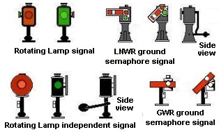
Some companies, including the GWR and LNWR, tried very small semaphore type ground signals, again with a lamp behind to give a clear indication at night, however these proved difficult to see.
Fig___ Examples of early pattern Ground Signals
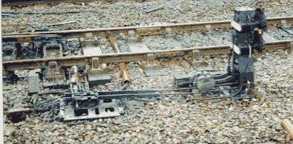
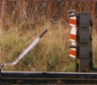
Early ground signals were operated by the point blades themselves. The danger is of course that the points might not have fully closed, so 'independent' signals were developed. These appear the same to the train crew but they are operated by a separate lever from the signal box or a local lever via wires and pulleys. The point mechanism was fitted with a hole and pin arrangement such that the signal could only be moved to the all-clear when the point blades were fully home. The photograph of the double ground signal (Fig___) shows the locking mechanism which is always mounted beside the relevant point as it is operated directly by the blades. In the shown example the mechanism is very close to the signal but it could equally be some distance away. The mechanism consists of a plate about eighteen inches (45 cm) square with a rod leading to the point blades and two rods running parallel to the track. The signal control wires are connected via the two rods and these can only be moved when the bar to the point is in the correct position.
Fig___ Ground signal interlocking mechanism
At about the time of the First World War a new design appeared, consisting of a more or less circular plate perhaps a foot in diameter, usually painted white with a red stripe across the middle.
The disc was pivoted in the centre so it could rotate, on early examples the disc was bolted to the arm of the miniature semaphore signal. When the red stripe was horizontal it meant stop, when at forty-five degrees it meant all-clear, for night operation small holes with coloured glass lenses were fitted to the plate and an oil lamp mounted behind to give a clear indication.
These rotating disk signals could be either upper quadrant or lower quadrant depending upon the preference of the owning company.
Where the original pivoting oil lamp signals still existed (the LNWR had quite a few of these for example), two separate discs were sometimes added to the two faces of the lamp. One plate had a horizontal red stripe, the other had a diagonal stripe, representing stop and all clear respectively, these plates had a hole in the centre for the original oil lamp lens. Some of these modified oil lamp signals survived into the 1960's.
There were variations in the design of disc signals, the LMS and the Southern Railway both had rotating discs consisting of fractionally more than half a circle with a flat bottom, the SR type had a slight dip along the lower edge, the LMS had a straight bottom edge. There were a couple of the LMS type still in use in 1997 at Stockport railway station south of Manchester. The GWR started with a similar flat bottomed shape (they only cropped off about the bottom third of the disk) but then used a full circle, and I believe this latter type became the standard for British Railways. The LNER standard upper quadrant ground signal was a full disc. These disc signals did not replace all the older designs, examples of the LNWR ground semaphore type remained in use into the 1970's and possibly the early 1980's, however where British Railways replaced ground signals they fitted the disc type.
Ground signals were only used for shunting purposes so the prohibition of two arms for different tracks on a single post did not apply, hence you will see disc signals 'stacked' two, three or even four high on a single short post. I believe there was a single example of a five disk signal (five disks mounted one above the other on a single post). The three disk type shown below was at the entrance to the DMU stabling sidings at Stockport, south of Manchester.
Fig___ Three-high disc type ground signal
As with the multiple home arms these are read from top to bottom as referring to routes from left to right, hence on a two disk signal the top disk refers to the route to the left and the upper disc that straight ahead or to the right. Multiple pivoted oil-lamp signals could not be mounted on a single post and where there was insufficient room for these to be placed side by side they were mounted separately one behind the other, with the rear lamp mounted on a longer spindle to show over the top.
The convention is to mount the signal, of any type, to the left of the track it controlled. Where a single disk was mounted between two sidings and it would be unclear which track it applied to a small white painted metal plate with a black arrow was added below the disk to show which track it referred to.
Ground signals showed red for danger and green or white (prior to 1893) for all-clear but, due to the proliferation of red ground signal lights in crowded yards, several companies used a white light for danger from about the time of the First World War. In the late 1920's the LMS and possibly other companies began using yellow lights and yellow miniature arms on ground signals which might be passed at 'danger' for shunting purposes.
Modern British Railways disc type ground signals have a small electric lamp in a housing to the upper right of the disk which illuminates the disk at night. The reverse side of the disk signal has a simple white semaphore arm, although this is only of real use where the rear of the signal is visible from the local signal box.
Fig___ Disc type ground signals
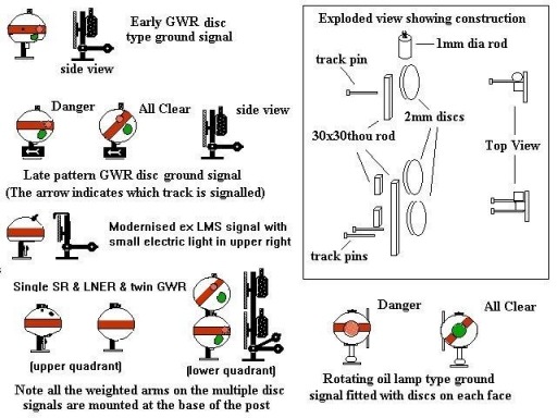
Ratio offer a kit of the later GWR/British Railways rotating disc signal in a pack of four single discs, these were unobtainable for a while so I made some up using a leather punch to make 2 mm diameter disks from 20 thou card.
To do this punch several disks with the punch, these will 'back up' inside the punch tube. Insert a panel pin into the punch and operate the mechanism to push the cut discs out of the tube. You may then need to put them between two sheets of metal (I used thick washers) and squeeze them flat with pliers or a gentle tap with a hammer. The discs were then stuck to a 6 mm length of 30 x 30 thou Slaters plastic rod. The lamp was a 2 mm length of 1 mm diameter round section rod carved about the top to represent the chimney. For the double disk type use an 8 mm high support and use 2 mm length of the same 30 x 30 thou rod to represent the square bodied lamps.
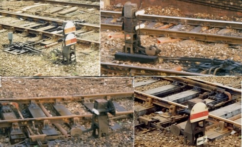
The ground signals in use at Stockport station on the London-Manchester line are an LMS design dating from the 1940's. The frame is from pressed metal and there is a small lamp on an arm which illuminates the front face of the signal. These signals were designed for use with the standard LMS cropped circle disks but the mountings are arranged at an angle so that on multiple disk signals full disks can be fitted with the top of the lower disk overlapping the base of the one above. In the 1990's all these signals retained the original cropped LMS disks.
Fig___ Photographs of disk type ground signals in 1997