Buffer stops and Track Maintenance Personnel & Equipment
At the end of a track there would be something to stop
things rolling off the end, usually referred to as a buffer stop (the
Americans call the 'bumpers'). These were not intended to stop a
runaway train but they would stop a wagon rolling along the track
fairly slowly. When positioned in platform bays or at the end of the
main line (at a terminus) they carried a lantern showing a red light
so the engine driver could see the end of the line. For N Gauge the
lamp can be made using a 2mm length of 40x40 thou strip with disks of
20 thou rod glued to one side and the top. The lamp was white with a
red lens. Glue this to the top of the buffer beam and glue a strip of
10x20 thou to the back of the lamp and buffer beam to represent the
mounting bracket.
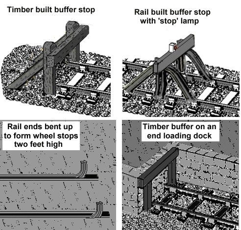
The most basic option was a heavy timber
beam, a sleeper would do, laid across the track. The railway
inspectors would not allow this as a permanent solution as they might
be moved but they were sometimes seen on light railways and often
used on industrial lines such as those serving a quarry or
brickworks.
A rather more permanent option, sometimes seen on
industrial lines and on some quayside lines, was simply to bend the
ends of the rails upwards by about two feet. The rolling stock wheels
then act as buffers, by making the stops two feet high they are above
the centreline of the wheel, which cannot then roll-over the
'buffer'. The sketch below shows such an arrangement used with inset
track on a quayside siding. I could not see in the photograph if a
diagonal brace had been added behind the curved rail. This would give
greater strength but similar curved sections of track were sometimes
used on wagon tipping plates and in at least two cases these had no
additional bracing fitted.
Next up in simplicity is the 'sleeper
built' buffer (a model of which is available in N from Peco), this is
a simple box built from timber sleepers set into the ground on end
and filled with earth.
Probably the most common type was the rail
built buffer stop (again a model is available in N from Peco). This
consists of lengths of rail bent to an inverted U shape and bolted to
the rails with the same sort of bolts used for fishplates. To these
were bolted vertical lengths of rail, extending up from the track. At
the top of these vertical rails there would be either a timber
sleeper or a couple of lengths of rail bolted to the frames at the
same height as the buffers on rolling stock.
A less common
variant was the timber built buffer stop, consisting of two heavy
(about eighteen inches wide by a foot deep) vertical timbers set into
the ground with a similar beam mounted horizontally at buffer height
and behind this were two more heavy beams set into the ground at an
angle to brace the frame. The vertical posts typically extended some distance
above the top of the buffer beam. These would require rather more
work to maintain ore replace than the rail built type (which could be
unbolted from the track), and could only be used at the end of a
siding where the track ended (the rail-built type could be bolted on
before the end of the track so the rails did not need to be cut to
length), this may explain why they were less common. The sketch was
made from an undated photograph of such a buffer stop in a
Metropolitan Railway goods yard but judging from the rolling stock in
the yard the photograph was probably taken in the late 1920's. Such a
buffer could be made using match sticks in N Gauge.
In end-loading
docks, where wheeled vehicles could be loaded onto flat wagons 'over
the buffers', I believe it was fairly standard practice to have a
timber beam at buffer height to protect the banked up platform beyond
as wagons were pushed up to the end of the siding. At a guess this
would be supported on sleepers with their ends buried into the ground
to either side of the track.
Fig___ Sketches of buffer
types
At the ends of long sidings you will sometimes see the track
banked up so the last sixty feet or so are on a raising gradient.
This served two purposes, it would help slow down a rolling vehicle
before it hit the buffers and also, when the siding was being
shunted, the engine driver would see the end vehicle rising as it
approached the end of the line. An example of this can be seen on the
carriage sidings on the approach to Manchester Piccadilly station.
Where a trap point was used, diverting run-away stock onto a
short stub line at the approach to a junction, there would be a set
of buffers at the end of the stub track but this track would have a
covering of sand, called a 'sand drag' to help slow down the
run-aways before they hit (and quite possibly demolished) the
buffers.
The cross timber or rails on buffer stops were sometimes painted red
but generally 'rust' colour would be a better description of the
metal type. As noted above a fitting for an oil (later electric)
lantern showing a red light was mounted on top of the buffer beam, in the centre, on tracks where the engine might be at the front of the train (dead ends in stations). These lanterns were not a standard
feature on sidings although I do seem to remember seeing some. The
lanterns themselves were white in the 1980's but I am not sure of the
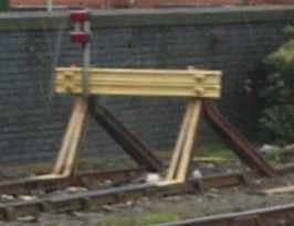
colour before then. From about the mid 1990's rail built buffers in
some locations (mainly sidings) seem to have switched to all-over yellow or 'rust' with yellow cross members. The example on the photograph (taken in 2004) is on the end of a lengthy head shunt and is equipped with an electric light.
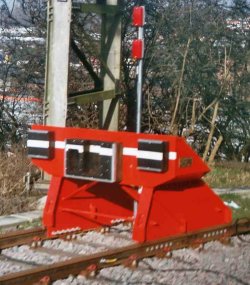
Fig___ Photo of modern rail-built buffer painted yellow
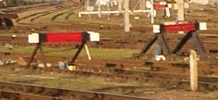
When sighted on the end of ordinary sidings the buffers of this type are painted in the same way but do not have the pole with the lights attached. In the North London area I saw a number of buffer stops painted red with white ends in late 2005. I have not seen this colour scheme anywhere else (yet).
Fig___ Photo of modern rail-built buffer
In
main line terminus stations there were experiments with hydraulic
buffers. I am not sure when these appeared but there was a model of a
set in the Hornby OO range in the 1960's. They consisted of a large
concrete block with a pair of very long shank buffers sticking out of
them. In Manchester Piccadilly station they used sets of rail-built
buffers clamped (not bolted) to the rails some distance from the end
of the track. Anything running into these would push them along the
track, absorbing the energy. Again I am not sure when these were
introduced but I believe buffers of this type replaced the expensive
hydraulic type. See also notes in italics below.
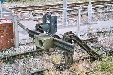
More
recently buffers have disappeared from rolling stock, notably the
more modern DMU's which favour the Scharfenberg combined buffer
coupling. The photograph below shows an old rail-built buffer stop at
Altrincham tram station that has been modified to handle this new
type of coupling (fitted to the Manchester trams). The vertical
supports which once carried the timber buffer beam have been cut down
to the same height as the U frames, the part of the U which used to
extend forward of the beam has been cut away and two cross-rails have
been added lower down fitted with a specially designed stop block. As
this is the end of the line there is a red light mounted above the
buffer beam but for some strange reason this is actually a signal, linked to the railway control
centre at Deansgate Junction in Manchester, and even has a plate
attached to identify its number (DJ 509). This may have been set up as the original lines from this platform ran on into a set of sidings and there may have been a plan to use these in the future. There is still a trailing cross over between the main railway line
and the tramlines at Altrincham, allowing diesel trains from the main
line to access the tram lines (to allow ballasting and the like). It would have been possible to establish a small goods handling yard but in the event the local council and the people charged with administering the old BR property decided that yuppie mico-flats and cafe-bars were preferable so the area has now been built up.
Fig___ Modern buffer stop with Scharfenberg stop
block
I
posted a question about these buffer stops on the news group
uk.railways and received a number of informative replies (note the
couplings mentioned are described separately under Rolling Stock
Construction). These are summarised below -
There are now
many different types of couplers in use, Buckeye, tightlock,
Scharfenberg, BSI are all in use on Diesel and electric units in the
UK. The London Underground uses a different design on its passenger
trains, Buckeyes on its engineers vehicles, and older trains used to
be fitted with Ward couplers, I'm not sure if any are still in
departmental use. Blocks of wood or other material shaped to accept
these various couplers are quite common, and can be fitted to various
designs of stop block.
I will make one comment on the one shown
in your photograph, I wouldn't want to be riding in a vehicle which
hit it at any speed. I have had the experience, many years ago of
being in a train which hit a fixed rigid stop block at about two
miles per hour, and it was quite a jolt, not pleasant, and I
certainly wouldn't want to do it any faster.
For many years large
hydraulic buffers were installed at passenger termini, they are
becoming much less common now, but London Waterloo still has them,
with an extra beam mounted in front of them, now that most passenger
trains do not have side buffers, but central automatic couplers.
These work by the train pushing back a piston, which expels water
from a cylinder, through a small opening, and therefore retard the
train over a certain distance. Typically they can be pushed back, a
metre or two, depending on the size. They were often gas heated, to
prevent freezing in winter. There is also a similar but oil-filled
hydraulic buffer, which has a large reservoir on top, one of the
District Line tracks at Ealing Broadway still has one.
Having a
train retarded over a metre or two is better than hitting a dead
stop, but the greater the distance the better. The modern solution is
a rigid metal structure, similar in shape to a rail-built buffer stop
but of welded steel construction. Rather than being rigidly attached
to the track, the rails pass under it, by way of a friction clamp
device on each rail, allowing it to be pushed back along the track a
considerable distance. Shaped blocks are normally fitted to these, to
fit the train couplers in use. Sometimes additional friction devices
are fitted to the rails behind it, which it would push back if it
reached them, gradually increasing the retarding force.
Sometimes
a sand drag is installed in front of a buffer stop to slow down a
train.
Modern practice is to allow as much space as possible
between the normal stopping place of a train at a terminus, and
anything solid which it would hit if it overran. At Stratford station
on the Jubilee Line it's quite a walk between the station concourse
and the first carriage of the train, probably more then an extra
carriage length of track.
I was working in Waterloo offices
one day when a train hit those hydraulic buffers. Although there were
no injuries - so the buffers had done their job properly, BR paid
quite a lot of money in compensation to people whose clothes were
ruined by the dirty water coming down from the roof.
By 2004 new buffer stops were appearing to handle the range of buffered and non buffered stock in use. The example below is situated on a siding close by Manchester Picadilly and has facilities to handle a range of buffer and coupling types.
Fig___ Modern steel plate buffer stop with buffer pads and Scharfenberg stop
block
Track Maintenance
Personnel & Equipment
Mention must be made
of the railway staff who maintain the track, this is a continual
process and until the 1970's was largely un-mechanised.
For each section of
track there was a man called a 'lineman' who was responsible for
inspecting a section of track and effecting minor repairs. He walked the track every day
looking for faults such as a loose fish-plate or chock working loose
in a chair, mis-aligned track, subsidence due to mining or rock faces
in danger of falling. A solitary figure eating his lunch alongside
the track would be a reasonable adjunct to a model railway.
The hard manual work
of repairing or adjusting a length of faulty track was done by teams
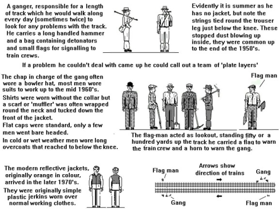
of 'plate layers' with a 'ganger' in charge. To protect the men as they worked a 'flag man' was
positioned up the track, armed with a flag and a horn. The horn was
used rather than the whistle as it could not be mistaken for a guards
whistle or a whistles used by station staff.
Fig___ Track
maintenance workers
Prior to the 1970's these men were not issued with uniforms and had to provide their own working clothes. From the mid 1970's onward the Health and Safety aspect was increasingly brought to the fore and the men were issued with more kit.
Up to the 1960's and I think into the early 1970's the chaps working
on the line, as in plate layers, were not (as I remember it) issued
with work clothing. I remember seeing a team of blokes working on a set of points in the
1960's wearing 'lounge suits' and overcoats, albeit with heavy boots. Some wore flat caps and the chap in charge had a hat with a brim. National Service was still in effect at the time and they may have been ex-forces men wearing their 'demob suits' (cheap suits issued to the men when they finished their period of service and were 'de-mobilised'). Most people did not own cars so overcoats tended to be longer than the modern 'car coat', typically reaching down to the mid calf. Standard gaberdine coats and ex-army woolen greatcoats were often used by men working outside. The bright yellow 'oilskin' coat (made from cotton treated with oil and wax to make it totally waterproof) was not popular as it tended to chafe and became stiff in cold weather. The rubberised fabric overcoats called a Mackintosh (or 'Mac') were completely waterproof but did not breath so they made you sweat a lot. They were handy when acting as a fog man but less suitable for heavy work, people sometimes cut these down to make waterproof jackets.
In the mid 1960's experiments were conducted with 'high visibility' orange clothing, the first simple jerkins as shown above were introduced in about 1970. By the mid 1970's the dayglow or international
orange plastic waistcoats were standard issue for track side workers and yellow waterproofs were widely issued (these were rubberised material and not very popular with staff). By the early 1980's hard hats were becoming increasingly common. The early 1990's saw the introduction of strips of retro reflective
white tape which soon became standard. By the later 1990's boiler suits, waterproofs, hard hats with ear defenders (hard hats are now worn even where there is no practical reason to do so) and
what appear to be standard issue pull-on work boots called 'rigger boots' seemed to be the
norm. By this time 'breathable' waterproof fabric such as Gortex was available and although expensive this has been widely used for coveralls, where the coveralls themselves are a dark colour they have retro-reflective strips on the arms and legs and often on the body as well.
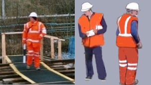
When working on an electrical junction box or similar a full 'high visibility' weatherproof suit is worn. This would be impractical for hard manual work (unless the weather is very bad) so modern plate layers favour a hip-length sleeveless hi-vis jerkin which has the retro reflective tapes sewn onto it. These jerkins are now designed to tear free if they become caught on something (this was found to be a problem for men working with shunters poles when wearing the early short type shown above). On some jerkins there is only a waist level strip (shown below centre) but most have a 'belt and braces' arrangement (shown below right) When the weather is cold the hi-vis over trousers are often worn as shown below right.
Fig___ Workers in 'hi-vis' clothing
I was not sure of the dates involved in the change to high visibility clothing so I posted a question on the uk.railway and uk.rec.models.rail newsgroups. Several people responded but the picture that emerged suggests that the change was not a simple matter, equipment and clothing being issued to different areas and different groups within those areas over time. The foregoing may however be taken as a rough guide to the sequence of events.
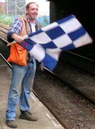
The chap in the photo below was photographed when working as the 'flag man' for a contracting company in 2006, he has been issued with a high visibility jerkin and carries the flag and horn.
There were many and
various problems that might need the attention of the plate
layers. For example track on curves tends to drift outwards due to
the force of the wagons passing through and has to be levered back
into line. Track that had settled too deeply into the ballast had to
be lifted up and the ballast shovelled back underneath it, worn or
damaged lengths of rail needed replacing and embankments eroded by
rain had to be shored up.
The railway
companies built special track-testing coaches, equipped with sensors
to measure the sideways and vertical movement. This was hauled along
the line and the measurements were recorded on paper strips. In
addition (on the GWR at least) a mechanical device was fitted which
squirted out some whitewash when the sensors detected too great a
deviation. The paper trace should have recorded the position of the
faulty track quite accurately but the whitewash was an additional aid
for the track gang to find the site of the problem.
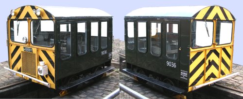
To allow men to travel along the line, for inspection or to do work, there were a number of 'inspection trolleys' produced, some were hand-powered but by the 1930s some were motorised. The 'pump trolley' often seen in American films was widely used in Britain, althouth not all were the same design (one type had three wheels, resembiling a motorbike with an out-rigger wheel, powered by pumping the 'handlebars' back and fore). The motorised example shown below is a Wickham petrol driven machine, these were certainly in use in about 1931 but the standard version had open sides. They could haul a four wheeler trailer carrying equipment, similar in size to the trolley with an open flat bed and raised ends about six inches high. The example shown is currently (2006) on loan from Marsh Engineering to the Manchester Museum of Science and Industry. I had difficulty finding information on these machines but Mark Brown was able to advise that this is probably a military version dating from about 1950, the civilian type usually had brown curtain sides and would (from the later 1960s) be painted yellow.
Fig___ Wickham trolley
Keith Gunner was able to advise-
As co-author of The Wickham Works List (published in 2004 and detailing almost 12,000 individual vehicles) I have a particular interest in all things to do with D Wickham &Co Ltd. My attention was drawn to your pages and especially the entry ilustrating the Wickham trolley at the Manchester Museum of Science &Industry.
I can confirm that this trolley is indeed a former MoD vehicle. It was built as Wickham's No.8196, a Type No.27 Mk III with a Ford 10hp engine, and delivered to Bicester Depot, Oxon, on 20/11/1958 where it became ARMY9036. It was sold out of MoD service in 1976 and after one or two private ownerships it became the property of Track Recovery Services of Altrincham (now Marsh Plant) by 2000. It has been at the Museum for quite a few months now.
Wickham built their first railcar, for the 3ft6in gauge Tal Tal Railway in Chile, in April 1922. Their last was outshopped in 1991. Including a few railcars built by their successors in the 1990s, nearly 12,000 vehicles of many varieties were produced to their designs.
The Type 27 Gang and Inspection trolley was introduced in 1948 and over 600 were built between then and 1990, of which 25 went to the Ministry of Supply / MoD between 1954 and 1960. It may be of interest to mention that the first of these "starred" in The Great St Trinians Train Robbery, that tale of schoolgirl mayhem filmed in part on the Longmoor Military Railway, and is extant in Yorkshire awaiting a projected sale.
A friend has established his own Fotopic website dedicated to On Track Plant with a specific section devoted to Wickham cars. Have a look at
http://roy-hennefer.fotopic.net/c779272.html
and you may be amazed at the variety.
For anyone wishing to obtain the above mentioned book, The Wickham Works List by Keith Gunner and Mike Kennard, it is available at £14-95 (incl P&P) from Dennis Duck Publications, 34 East Street, Fareham, Hants, PO16 0BY.
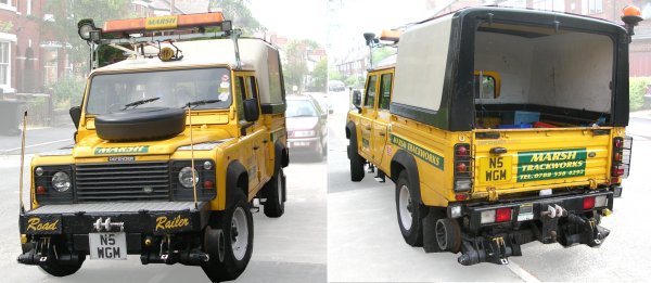
In the 1980s a number of 'road-rail' vehicles were deployed as track maintenance support equipment which have hydraulically operated flanged wheels, traction is provided by the standard driving wheels. These road-rail machines had been in use in industry certainly since the mid 1970s but I have found little evidence of their use on the main line railways before the later 1980s.
Fig___ Road Railer Landrover
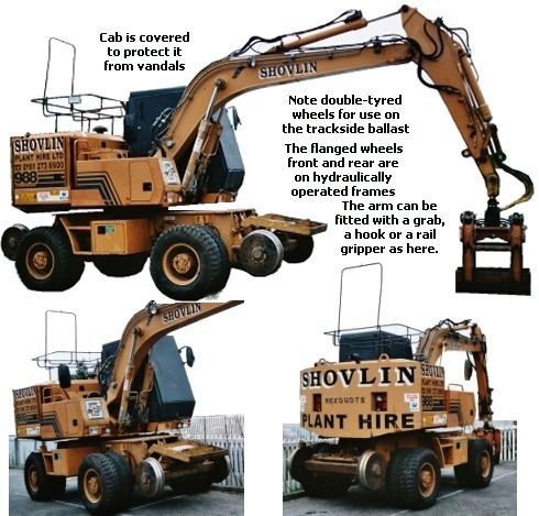
The railways have made extensive use of powered equipment, especially since the manpower shortage of the Second World War, one common bit of kit being the small crane (often used for handling lengths of rail. In the early days these were taken to the site on a flat wagon, the train was separated to make some room for it and steel channels were laid up against the end of the wagon to allow it to drive off over the buffers. As they have to trundle about on the ballast and often on rather soft ground beside the line they are almost always fitted with double wheels to spread the load. The early cranes had a lattice jib but from the mid 1970's the hydraulic articulated jib became increasingly the norm.
In the 1980's the road-rail crane appeared, basically a standard crane but with hydraulically operated frames mounted at each end and fitted with powered flanged rail wheels, allowing it to move along the line. These can be delivered by road to a suitable access point then travel along the line to where the work is being done.
Fig___ Track Maintenance Crane
Tracked vehicles, such as bulldozers, have also been fitted with hydraulically deployed flanged wheels however it seems unlikely that these use their tracks for traction and they may be towed along the track by other machines.
The early BR track
maintenance machines were painted green but the standard had changed
to yellow by the 1970's. The market leader is now the Austrian firm
Plasser and I understand a powered model of the standard tamping
machine should be available in N by late 1998.
Soil gradually works
its way into the ballast and prevents water draining through. This results in degradation of the track bed and produces uneven track. The old
method of putting this right was to simply replace the ballast,
shovelling the old ballast and soil into spoil wagons. Today there
are special ballast cleaning machines (developed before the second
world war but not regularly used until the BR built some in the
1960's), these new machines clean the ballast in place and only a
`topping up' is required. By the 1970s there were increasing numbers of specialised machines in use for track maintenance, some lift and level the track, others replace the ballast. These machines are furtive beasts, often only venturing out at night. I know little about these machines and have seldom seen examples although there are numerous web sites devoted to them where you might find further information.
One of the more common problems with track is that over time it settles down into the ballast and becomes uneven. The original solution, in use into the 1970s, was to take a long (20 feet) stout pole, this was pushed under the rail on one side and laid down on top of the rail on the other side. A team of men would then pull down on the free end to lift one side of the track so other men could shovel fresh ballast under the sleepers. This work took time and was expensive in manpower so to solve the problem the self propelled 'tamper' was introduced. The tamper first lifts the track, then vibrating steel splines are driven down into the ballast and pulled together to force the ballast under the sleepers.
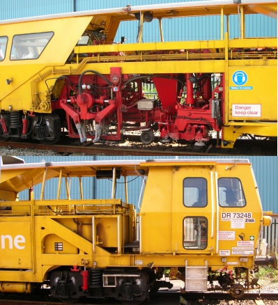
I wasn't sure what the machine shown below was, however when I asked on the uk.railway newsgroup where 'Kirk' confirmed this was a tamper and Charlie Hulme (another regular on uk.railway) informed me that -
DR 73248 is a Plasser & Theurer 07-16 Universal Tamper / Liner. The bits with the red arms hanging down under the curout in the body are the arms ('tines') that go down each side of a sleeper and compact the ballast below.
Charlie
Fig___ Tamper unit
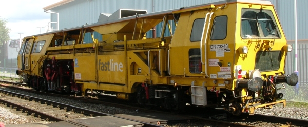
The detail views show the cab at one end and the operating section at the other in more detail.
Fig___ Front and operating section
This approach saved a lot of time and man power but it was found that it upset the natural compacting of the ballast and over time caused problems with the underlying trackbed. This allowed the track to sink back down rather faster than the old manual method, producing rough riding on the unlevel sections of track and requiring more frequent attention. The solution being explored in 2006 is the ballast blower, this lifts the track but then uses compressed air to force fresh ballast under the sleepers. It is hoped that this will retain the natural compacting of the ballast and not cause the problems with the sub base.
With the
increased speeds on the railway and the reduction in weight
(especially of the modern passenger vehicles) the slippery remains of
wet leaves falling on the line in autumn has become a serious
problem. The sticky mess of the rotting leaf mulch greatly increases
stopping distances and allows the wheels to slip when trying to
accelerate. The problem wet leaves interfering with electrical track
circuiting for signals (discussed in the following section) is at
least as serious as the problems of acceleration and braking of
trains.
With the old heavy steam engines, travelling at much
lower speeds wet leaves were much less of a problem but even so
various machines have been developed for this work. In the 1920's
open wagons were fitted with screw-down wire brushes to clean the top
surface of the track. British Railways set up an 'adhesion working
group' who's job it was to evaluate methods of removing the mess from
the rail tops. One machine brought in from Sweden uses wire brushes
to scour the track whilst another uses jets of very high pressure
water. It had been thought that, once a design had been settled upon,
it might have been possible to fit the necessary equipment to a
proportion of the motive power so that it cleaned the track as it
travelled along however I believe this approach was not taken up.
Following the fragmentation caused by the
botched privatisation of the railways this type of coherent
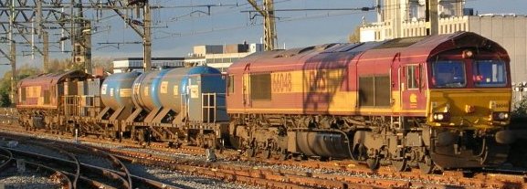
development has proved much more difficult. One system that seems to have found favour is the 'sandite' unit, this uses high pressure water to clean the muck off the track and adds a second spray which includes (amongst other things) powdered aluminium to improve electrical contact required by 'track circuit' train detection used in modern signalling systems. Early versions of this system used a pair of tank wagons with a converted GUV acting as a spray coach, usually with a Class 37 at each end (so it can run full speed in either direction). By 2006, when the photo below was taken, the equipment was being carried on two long bogie wagons sandwiched between two Class 66 engines.
Fig ___ Sandite track cleaning unit
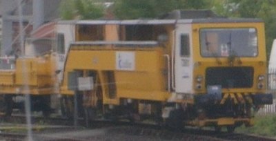
The most recent system to have found favour for permanent way work is the MPV or multi-purpose-vehicle, based on the German Windhoff Cargo Sprinter (a self contained, self propelled container carrier) which has a long flat bed with a rectangular cab at one end. These have a selection of pods, tanks etc they can carry depending upon the duties to which they are put. The tanks used resemble those on the sandite unit shown above. I have even seen a photo taken in 2006 of two such units owned by Network Rail top-and-tailing a rake of half a doen or so OTA timber wagons in Wales, I gather there was a cable run along the train allowing them to work as a multiple unit. The rake had a Class 37 added as insurance, I suspect this may have been a trial run, the 37 may have been required to allow the use of electronic token block working on the line. I was not able to find much information on these units but Brian Williams was able to advise-
They're based on the German 'Cargosprinter' container-carrying DMUs, and can carry a wide variety of modules for different tasks. Apart from the rail-head treatment and weedkilling ones mentioned, they can be used for catenary maintenance, P-W work etc. The modular system was derived from that designed for the Eurotunnel works
trains- the units used on CTRL now use the Eurotunnel facilities at Cheriton to exchange modules.
The example shown below is (I believe) one of these units, it was photographed from a moving train, parked on a remote siding on a dull day, the rectangular form and all over yellow paint job are characteristic of these machines.
Fig___ Rail maintenance unit
Railtrack planed to
renew 1,200 bridge spans, 2,500 km of rail, 5,500 km of sleepers and
over 6,000 km of ballast between 1998 and 2008. The actual work was to
be subcontracted to track maintenance companies, mostly based on
three year contracts. With the end of Railtrack in 2001 the entire
plan has been reviewed by its replacement Network Rail but as far as
I am aware the details have not yet (2003) been published.
^
Go to top of page
International Good Guys ~ Substituting for Prime Numbers since 1971 ~ Site maintained by

All material Copyright © Mike Smith 2003 unless otherwise credited