Rolling Mills, Wire Drawing and Pipe Works
Wrought iron and mild steel are both mailable, when heated they can be shaped using hammers or rollers, blacksmiths use these materials to produce shaped goods from rod and bar. Goods such as nails and chain were produced in 'cottage industries' (the workshop being attached to the rear of the maker home) from iron rod (for chain) or strips of wrought iron cut from sheet (by nail makers). Wire drawing produces better quality lengths of steel and this material has replaced the wrought iron used for chain and nails.
Steel rolling mills and wire-drawing factories tend to be large, again exchange sidings with a works painted on the back scene is probably the best bet. The former took in slabs and billets of steel and produce rails, girders and the like, a characteristic feature would be the rollers mentioned above.
Rolling Mills
Unlike cast iron wrought iron can be heated and rolled into long strips or sheets (rolling iron into sheet and bar form had been practiced since the 1600's but in 1783 a chap called Henry Cort, who owned an iron works, developed a method of producing iron bars quickly and economically in a rolling mill with grooved rollers. The following year he patented his 'puddling' process for converting pig iron into wrought iron and these two inventions had a significant effect on Britain's iron-making industry. Due to his partner being found guilty of fraud Cort's patents were confiscated and thrown open to all and British iron production quadrupled in the next 20 years. Cort's machine represented a real improvement) as the grooved rollers produced bars of standard thickness and allowed bar-iron to be made at a much reduced cost, the market price of iron fell by about half as Cort's system spread.
In a rolling mill ingots of wrought iron (or mild steel) are heated to red heat and passed between rollers to form them into sheets and useful shapes, the rollers can even emboss a decorative pattern on the metal. The rollers were typically four or five foot long and about a foot or eighteen inches in diameter. At each end was a short stub, perhaps nine inches in diameter and a foot or so long, which served as the axle for the roller.
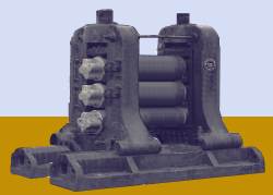
The example sketched below is typical, there are three rollers, the hot metal rod is fed in between the top two, which draw it through shaping it as they do so. When the back end of the strip drops out it is picked up and fed back through the lower set, allowing multiple passes through the rollers before the metal cools too much to work. These machines would be located in the centre of a large room, in a long building typically as high as a two storey house.
Fig ___ Typical rolling mill
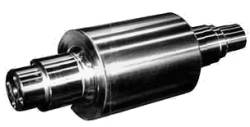
Henry Cort's rolling mill was designed to accept different sets of rollers to allow a range of shapes to be produced. Large numbers of spare rollers were often seen piled up about the place, usually outside and visible, so modelling these sets the scene for a rolling mill. The illustration below shows a typical roll (this one is for rolling out flat sheet), the exampe shown is brand new, those seen piled up in the yard of the works were a uniform dirty rust colour.
Fig ___ Typical roll used in a rolling mill
Probably the best option is to use telescopic sections of Plastruct tube for the main body of the rollers, held in a hand drill and turned against a Swiss file to add the grooves, sections of tube of progressively smaller diameter are then added, the centre tube being filled at the ends with Milliput. For bulk production I used wooden cocktail sticks with strips of paper wound round them, when painted (dirty dark grey) they looked acceptable to me although they were all 'flat plate' rollers with no grooves. The 2mm Scale Association offers a simple one-piece body kit (which can be fitted to a Peco chassis) of a flat wagon with wooden troughs intended to carry these rolls.
Ninety percent of steel is passed to rolling mills of one kind or another, a modern steelworks often includes some form of rolling mill but this might only part process the steel. Output from such a mill would include 'blooms' (fairly large blocks of square or roughly rectangular cross section usually with rounded off edges and with a cross sectional area of more then 36 square inches), 'billets' (square section bars perhaps four or five inches square) and 'slabs' (lengths of rectangular section). Plates are sheets of steel or iron which are more than a quarter of an inch thick, anything thinner than this is classified as sheet.
A lot of zinc passes through rolling mills, it was used (amongst other things) to make perforated metal sheet to act as fly-screens in pantry windows and for dome shaped covers to keep flies off food (commonplace into the early 1960s).
Modern strip mills were developed in 1923, based on work done by a chap called John Tytus, but strip mills did not catch on in Britain until the 1950's. These produce very long lengths of steel strip anything up to eight feet wide and up to about three quarters of an inch thick (although most is thinner) which is rolled into a coil whilst still hot and shipped on railway 'stripcoil' wagons.
Modelling the steel strip coils and their associated rolling stock is discussed in the section on Wagon Loads & Materials Handling - Wagon Loads - Metals.
Wire drawing
Mechanical slitting of iron sheet had appeared as early as 1600 (using water wheels for power), the bundles of cut strips were passed to nail makers (who had their workshops built onto the rear of their homes). Hand made nails were expensive and by the early twentieth century nails were being made in machines using steel wire.
Wire drawing was developed in Germany in the 14th century. Until the 19th century the wire was pulled through the die by hand, by the end of the 19th century all wire was drawn by machine. Metal rods are pulled through a series of progressively smaller tungsten carbide dies to produce large-diameter wire, and through diamond dies for very fine wire. The die is funnel-shaped, with the opening smaller than the diameter of the rod. The rod, which is pointed at one end, is coated with a lubricant to allow it to slip through the die. Pincers pull the rod through until it can be wound round a drum and the drum then rotates, drawing the wire through the die and winding it into a coil. All of this is done inside a large building, whch makes life easy for the modeller.
The wire drawing works are supplied with smaller ingots or lengths of thick rod, the wire and rods they produce are both shipped out as coils although straight rods are also a regular cargo. The resulting wire is used in nail making, steel wire for baling, bedding and seating, cold-heading and fasteners, electro-galvanized, hose-amouring and general wire-working applications. Two main centres for wire and rod is the Cardiff Wire and Rod works in South Wales (this closed in 2002, part of the colapse of Allied Steel and Wire, due mainly to arguments between bankers, it re-opened in 2003 under the ownership of the Spanish Grupo Celsa) and Carrington Wire Limited (bought by Russia's Severstal in 2006), but there used to be a great many smaller works dotted round the country.
Outgoing cargo would be coils of wire, for which the railways built special wagons.
The wagon shown below is a simple conversion from the standard plate wagon and can be modelled in N Gauge using the Peco plate wagon as a basis.
Fig ___ British Railways Coil-E wagon
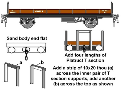
Making the coils is tedious, you need a paper core tube, around you wind monfillament fishing line, building this up at an angle to for a series of bulges to resemble a series of coils leaning toward one end. See also 'Wagon Loads and Materials Handling - Wagon Loads - Metals' for photographs of wire coils and a thoughts on modelling them.
One minor point is that a wire drawing works would justify a wooden bodied tank wagon for chloride of iron liquor (these wagons are described in the section on Rolling Stock - Rail Tanks).
Steel wire is made for a wide range of applications, farmers need galvanized wire (coated with zinc, which does not rust), barbed wire and wire mesh for fencing. Needles, pins, nails, and rivets are all made from wire and steel ropes and cables are made by laying up strands of thin wire. Wire weaving works produced a range of goods, mainly with fine wire, such as mesh for flour sieves and motor car oil filters and screens to keep out insects.
Galvanised iron was developed in France by a chap called Sorel, galvanising consists of coating the metal with a layer of zinc which does not rust. It was increasingly used after about 1880, as well as sheet metal barbed wire was also commonly galvanised which allowed farmers to fence off large tracts of land easily. Galvanising today is done by drawing the strip (or dipping a plate) into a bath of molten zinc. As the word galvanising suggests the original method was to use electroplating, today this is only done with zinc where a thin and very even coating is required.
At a galvanising works the metal is first 'pickled' by dipping it into acid to remove the scale and oxides from the surface. Various acids are used for this work including phosphoric, sulphuric and nitric all of which can be shipped in railway tank wagons. The wire or sheet is treated with a primer then dipped in molten Zinc at 440 degrees Celsius.
Pipe and tube works
Broadly speaking there are two types of tube, seamed and seamless. The former are made by bending metal strip to the required shape then welding the edges together, the latter are made in various ways, the most common being to start with a block of metal with a hole in it and draw this through a die to reduce its size. Cast iron pipes are cast in a sand mould and hence have no seam, these were widely used for town gas and water pipes as cast iron is resistant to corrosion. Other methods of producing seamless pipe are discussed below.
Many firms which had specialised in gun barrels reacted to the drop in demand after the Napoleonic wars by turning to making tubes for gas and water pipes. In 1871 a Law was passed stipulating that all water pipes in London had to be made of cast iron (these were already in use but combined with wooden and stone pipes). This change allowed higher pressure and for the first time taps did not have to be on the ground floor. Among the better known pipe works are the Stanton and Staveley establishments in Derbyshire and the Stewarts & Lloyds works at Newport in Monmouthshire.
By the later 1820's pipes were being made from long strips of wrought iron sheet (called 'skelp') which was pulled through a circular die to form it into shape, the edges welding together due to the pressure (although they were also often heated I gather). For more on welding see also Lineside Industries - Industrial and agricultural vehicles and equipment. This method remains the single most common method for pipe making, although steel has replaced iron for the skelp (since the 1950's strip steel has been shipped to pipe works in rolls, the railways have provided specialised vehicles for the carriage of these rolls).
For pipes of between about one inch and four foot diameter the skelp is heated and passes through a shaped funnel called a 'bell' which bends it into a tube shape. The hot metal edges are pressed together as the tube forms and weld together.
Small pipes (less than half an inch outside diameter) require a slightly more complicated arrangement where the metal is first heated then shaped as above but passes over a spike called a mandrel mounted between the rollers. At the other end of the scale large pipes are made from sheet metal by bending it into shape then welding the resulting join. The welding has often been done by passing electricity through the joint since the 1920's, the alternative being to weld using gas or arc welding equipment.
For very high temperatures and pressures, steel 'seamless' pipes are made with walls of up to six inches thick. This is done by heating a length of steel round bar then spinning it (very fast) between two cone shaped rollers. The spinning causes the centre of the bar to open and the rollers are arranged to slowly draw the bar through and pass it over a shaped spike called a 'mandrel'. This technique was developed by a German engineer called Reinhard Mannesmann (1856-1922) and the one of the first plants was opened in Swansea (South Wales) in 1887.
Due to the limitations of the iron and steel making industries large diameter tubes, boilers and the like, were often made by forming up several metal plates then riveting these together. This method is still used for 'one off' jobs.
Cast iron water pipes were rust-proofed by dipping them in hot baths containing a mix of hot coal tar and mineral oil, the second dip was at a lower temperature to avoid melting the first coat. Pipes for gas were coated with a black material made by dissolving coal in coal tar, most gas and water pipes were therefore black in colour.
Fortunately virtually all of the above processes are done inside large buildings, so we need only provide quite minimal external clutter to set the scene.
The main building is suggested as the Nuremberg locomotive works and pair of workshops from Pola and the name Wm. LANLEY PIPE & TUBE MFR is suggested as it is comprised of straight lines and so would be easy to paint on the embossed stonework of the building. Stockpiles can comprise pipes made from drinking straws, the hollow shafts from Q-Tips and Rizla cigarette papers cut in half lengthways, rolled round a length of florists wire and gummed to form thin walled tubes. The covered extension between the main works and the workshop is simply the Ratio corrugated roof with an 'I' section Plastruct supporting frame. The gantry crane could be purchased or home made.
Incoming cargo would be raw material in the form of ingots and sheet metal (post world war two this would include strip steel coils), coal for boilers, van loads of smaller items and tank wagon loads of coatings and or metal pickling fluids. Outgoing would be tubes ranging from 0.5mm up to 16mm in diameter (anything larger would constitute and 'out of gauge load') or even a complete cement kiln in sections. This latter is illustrated in the book 'Freight Wagons & Loads on the GWR and BR Western Region'.
Railway rolling stock would include three, five and seven plank open wagons, mineral wagons (delivering coal) tube and pipe wagons, Peco twin bolsters, low machinery wagons, trolley wagons and well wagons, coal for the boilers, vans (in and out) perhaps tank wagons carrying coatings or metal pickling fluids such as phosphoric acid (available from Peco).
Fig ___ Pipe works 1880-1990
Notable British Pipe and Tube Manufacturers
Stewarts and Lloyds, formed by the amalgamation of Glasgow based and Birmingham based companies in 1903, from the 1930s production was centred at Corby, Northamptonshire, where they used locally mined ore to produce steel and tubes. This plant closed in 1980. Stewarts and Lloyds bought out a number of other companies and made pipes around Glasgow as well as operating a large pipe and tube plant at Newport in Monmouthshire. This comapny was also the owner of a number of subsidiaries including several coal mines
Stanton Iron Company, (renamed Stanton Iron Works Company in about 1900) was based at Ilkeston in Derbyshire, started in the 1840s. Notable as suppliers of cast metal pipes (which often had 'STANTON' printed on their sides in white). Merged with Stewarts and Lloyds in 1939 who merged the pipe making side with the Staveley Iron and Chemical Company production in 1960 (thereafter pipes were often marked STANTON AND STAVELEY).
Staveley Iron and Chemical Company Ltd was based at Staveley, near Ilkeston in Derbyshire, their registered offices were in Chesterfield. The Staveley area was used for iron quarrying from the 17th century and in the 1860s the Staveley Coal and Iron Company was set up, pipe production was greatly exapanded within a few years. The firm was nationalised in 1947, denationalised in the 1950s. It was sold to Stewarts and Lloyds in 1960 when it was merged with the Stanton company. As with all these large concerns SICC had a number of subsidiaries, notably the British Soda Company (who operated from a salt mine in Sandbach in Cheshire from 1919).
Stanton Staveley was renationalised in 1967, becoming part of the Tube division of British Steel. The combined Statnton Staveley operation became Stanton PLC, at some point they also began making concrete tubes and lamp posts. During the early 1980s Stanton became part of the French Pont-a-Mouson Group and part of the French Saint-Gobain Group in 1985. By the early 21st century the British Saint-Gobain Pipelines operation incorporated over 40 companies across the country but with most operations centred in Derbyshire and employed over 18,000 people. In about 2006 it was anounced that most of the Stanton and Staveley plant was to close
^
Go to top of page
International Good Guys ~ Making the world a
better place since 1971 ~ Site maintained by

All material Copyright © Mike
Smith 2003 unless otherwise credited