Scrap metal yards, Foundries and Forges
Scrap metal
Scrap metal has been reprocessed since the mid 19th Century and more recently it has become a major business as it is often cheaper to recover special steels than it is to produce them. Up to the 1920's separating the metal involved hacksaws and hammer and chisel work. Oxy-acetylene cutting gear was developed in the very early part of the century but it took a while to become common in scrap yards (see also Lineside Industries - Industrial and agricultural vehicles and equipment for more on welding and cutting).
Scrap metal merchants recieved a lot of waste material from local engineering works this might include (depending on the nature of the works) three plank wagon loads of rivet hole punchings, swarf from machine tools and hammerscale from a forge. A lot of this material went direct to steel works but a proportion was dealt with by the scrap metal trade, mostly delivered by road but usually shipped out by rail. Rivet punchings can be represented by fine sand painted black with traces of rust in N. Swarf is light stuff, some coiled in a spiral like a watch spring but most in a long helix like a coil spring. This was piled just above the top of the side on 16 ton mineral wagons, quite shiny when new and difficult to represent in N although the grey type of anti-static foam which is quite an 'open' material, with a rinse of very thinned matt aluminium and light grey paint is acceptable. Hammerscale is the the flakes of metal that fall to the floor whilst the metal is being worked (notably in a forge), this was dense and heavy so again a three plank wagon load, very fine sand painted black with traces of rust.
They would also receive odd bits of metal recovered from decomissioned plant, mainly sections of plate and girders. A proportion of the recovered materials would go out by road to local firms but sorted material was also shipped out by rail for reprocessing. This would have been a loose jumble prior to the widespread introduction of the hydraulic crusher in the 1970s.
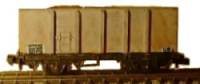
Scrap yards make for interesting traffic, including old railway stock. Many were rail served and scrap remained a regular (if not very valuable) cargo for the railways well into the 1980s and probably still today. Scrap was carried in standard open wagons, usually mineral wagons, and elderly vacuum braked wagons remained in this traffic after most of the system had switched to air braked stock. BR re-bodied some twenty one ton mineral wagons specifically for scrap traffic in the 1960's, fitting only a single door on each side, toward the left hand end. Standard Railway Co built a fleet of similar looking scrap carrying wagons on a 15' wheelbase air braked chassis and coded POA in the late 1970's.
n the 1980s Mr R. Snelling of the N Gauge Society produced a range of resin kits including a one piece loaded body kit for one of these wagons as shown below.
Fig ___ Air braked scrap wagon model
The British Steel Corporation (formed in 1967) ran regular loads of scrap by rail to both Scunthorpe & Sheffield and in the 1980s Sheerness Steel commissioned Procor to build them some large bogie open wagons capable of carrying both scrap and finished steel product. The Sheerness works is laid out in such a way as to facilitate this double use of the rolling stock, most steel works are not laid out in the same way and hence the scrap vehicles are not used to carry finished goods. (I believe the Sheerness works closed in 2002, part of the collapse of Allied Steel and Wire)
By the 1980s air braked HBA hoppers were being converted for 'shredded metal' and re-coded HSA (I cannot see any visible changes to the wagons in photographs). Some PO designs were used, examples from the air braked wera have been illustrated in the section on Railway Freight Operations - Metals Traffic. Available models include the NThusiast Resprays long bogie air-braked JXA Sheerness Steel Wagon (NTR.1) and Bernard Taylor (Taylor Plastic Models) offers a kit of the PNA/SSA four wheeled scrap wagons to fit the Taylor-Farish air braked chassis.
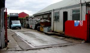
A scrap yard requires a weigh bridge as almost everything arriving and departing is valued by weight. The example shown below is at the entrance to Davidson's yard in Broadheath (they deal in all forms of scrap both ferrous and non ferrous).
Fig ___ Scrap yard weigh bridge photographed in 2007
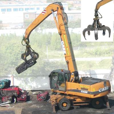
Scrap yards usually featured at least one crane usually with quite a long jib and at a larger yard there was often a gantry crane. Note there were steam powered cranes mounted on railway chassis and equipped with electro-magnets in use at scrap yards in the 1930's. Pre war equipment was all cable-operated, hydraulics only really developed during the war, and hydraulic equipment only became dominant in the 1960s. By the 1970s the hydraulic crane was commonplace and cranes equipped with hydraulic grabs as well as magnets were in widespread use, the example shown was photographed in Bennett Bros car breakers yard just South of Manchester by Mr Ian Mackay in 2007 (car breakers are considered in more detail below). The inset (top right) shows the grab in the open position.
Fig ___ Scrap yard crane photographed in 2007
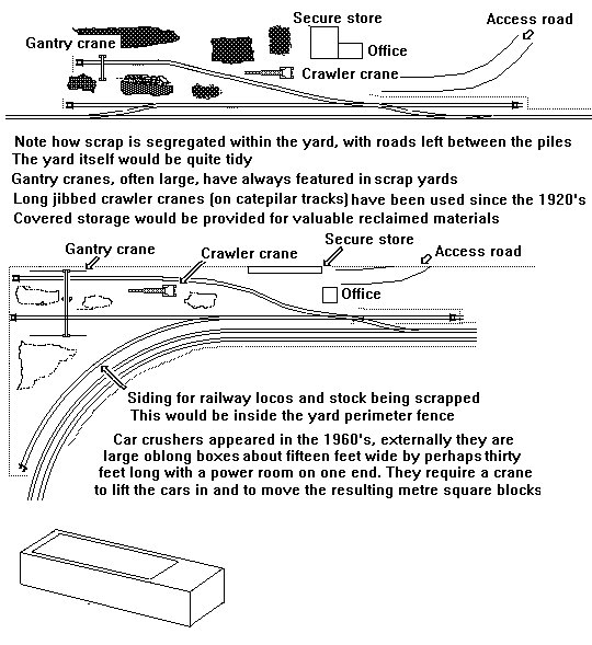
The sketches below are based on a photograph of a rail connected scrap yard photographed in the early 1980's. Clutter in the scene would include large piles of partially sorted material, a crane (often rail mounted), oxy-acetylene cutting gear and some covered storage for the weather sensitive or particularly valuable items. From about 1970 a crusher may have been on site to compress recovered material such as car bodies for shipping to the customer.
Fig ___ Suggestions for a scrap yard
Since the 1960's scrap cars have come to dominate the market in terms of volume, such yards feature wheel-less cars piled anything up to twenty foot high so you would require a plentiful supply of vehicles (Pola offer a car scrap yard in their N range which comes with a full compliment of partially broken up cars). Firms dealing in scrap vehicles are often located alongside the railway but seldom these days rail-connected. The sheer number of cars being scrapped, and the complexity of recovering the different materials from them, lead to the establishment of breakers yards, who take in old cars and recover the materials (and often the parts) used in them. This material is then sorted and placed in sheds for sale with the unsaleable scrap metal shipped direct to the scrap merchants as pre-sorted scrap in bulk.
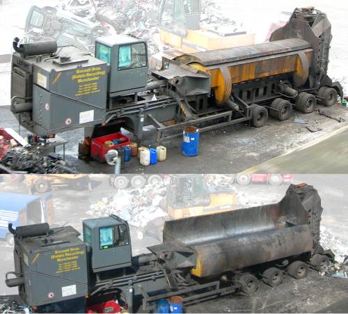
The car-crusher was invented in the 1940s (building on the refinement of hydraulic systems during the war) and introduced in British scrap yards in the 1960s, the 'car crusher' is usually a 'bailer', so called because it crushed the material into a rectangular block resembling a bale, there is an alternative that simply crushes the car flat but these seem much less common. These are not only used for crushing cars, they can be used for any material that would benefit from 'baling', this means the material does not need to be strapped down to a pallet and is less likely to shed bits when on the move, for example one firm handles the aluminium 'litho' plates from a printers, forming these into bales which are easier to ship to the recycling plant.
The example below is in use at the Bennet Bros car breakers yard just south of Manchester (the photos were kindly taken by Mr Ian Mackay as he passed the yard on the tram). The photographs show the crusher in both closed (upper) and open (lower) positions. This machine is being used to crush general segregated scrap into blocks about five feet long by about two feet square.
Fig ___ Car crusher photographed in 2007
The advantage of the car breakers is that they require very much smaller premises and have comparatively little 'stock' on site, the cars are brought in, broken down, elements such as the body are crushed and the lot is shipped out. For a layout set from the later 1960s these offer a minimum space alternative to a proper scrap metal merchants.
Foundries
A foundry pours liquid metal into moulds to make castings, these can be iron, steel, bronze, brass, aluminum, magnesium alloys, or various alloys, which often include lead, tin, and zinc (notably white metal used for many small modelling accessories). At an iron or steel works the areas where the metal is cast into pigs, billets or blooms is called a foundry although the liquid metal is poured from a very large ladle, holding several hundred tons of material. The discussion below concentrates on smaller foundries which might form a smaller line side industry. These foundries will specialise, iron and steel at one, bronze, brass and aluminium at another with specialist firms working with other materials.
An iron foundry takes in pig iron to make cast iron, you would normally have a foundry associated with an iron works but there were also small establishments catering to local industry (most towns had at least two small foundries) and larger engineering works often had their own foundry on-site. Iron foundries tend to be larger than the other types, they generally produce larger castings.
At a foundry producing cast iron goods the pig iron, and perhaps some scrap iron, are mixed with coke in a furnace called a 'cupola' and re-melted. The re-melting process removes more of the impurities but cast iron still has a lot of carbon in it and is brittle. The cast iron drawn from the cupola is however very fluid can be poured directly into moulds with intricate shapes. Cast iron is easy to machine and is very strong under compression. To harden the metal as it sets in the mould metal plates are added to the mould that produce rapid local cooling, similar to the tempering done at a forge. From the early part of the twentieth century steel was sometimes added to the mix to give 'semi-steel'. Once the cast was broken out of the mould they were passed to a 'fettler' for 'fettling', which means removing flash and other errors from the surface of the cast. The fettlers also look for cracks in the castings, at the moment one common method used in Britain relies on Azo dyes, although in several other countries the use of these dyes was banned in the 1990s.
A typical small iron foundry cupola consists of a heavy base with a tall metal tube extending about twenty five feet upwards, that is through both floors of a two storey building and sticking out of the roof. Not all foundries had a building round the cupola, in smaller establishments this might be in the open as shown below. On the upper floor was a door or hatch in the side of the tall tube to allow the adding of raw materials, called 'charging', at the bottom was an arrangement for tapping off the molten iron. The very base of the cupola was raised perhaps three feet above the ground and was fitted with drop-doors to allow the residue of red-hot slag to be dropped out. This could be modelled, adding a red LED under some PVA glue 'slag' with a small smoke generator feeding through a pipe from under the baseboard. This gives the impression of 'something going on' without the complication of having people moving about.
The cupolas once running could be kept going for several days if sufficient raw material was to hand. The resulting molten iron is tapped off, usually into a container, then poured into moulds to produce ornamental structural pieces, motor car engine blocks, manhole covers and the like.
The molten metal can be run off into a sand mould but where complex shapes such as balls were required a multi-part mould is used. In this latter case it was usual to run the molten iron into a bucket or ladle and pour from this into the mould. At larger works the ladle would be a big steel bucket suspended from an overhead gantry type crane at a small establishment it would be a small crucible carried by two men using a pair of long steel rods. Multi-part moulds can be made in various ways but if a large number of similar items were required they would be made of steel. These were formed in a series of circular units called 'flasks' which could be stacked on top of one another, the moulds being connected by a network of cores called the 'sprue'.
These flasks would be stacked and clamped together and the molten metal could then be poured into the tops of the sprue holes to produce several layers of the desired shapes. After cooling each layer is lifted off by a crane so the castings can be removed. Also associated with a foundry would be a workshop an possibly a stores for the pattern makers. These skilled individuals made the shapes for impressing in the sand to form a mould. The patterns were generally made in wood. The sketch below shows a small foundry.
Fig ___ Small foundry
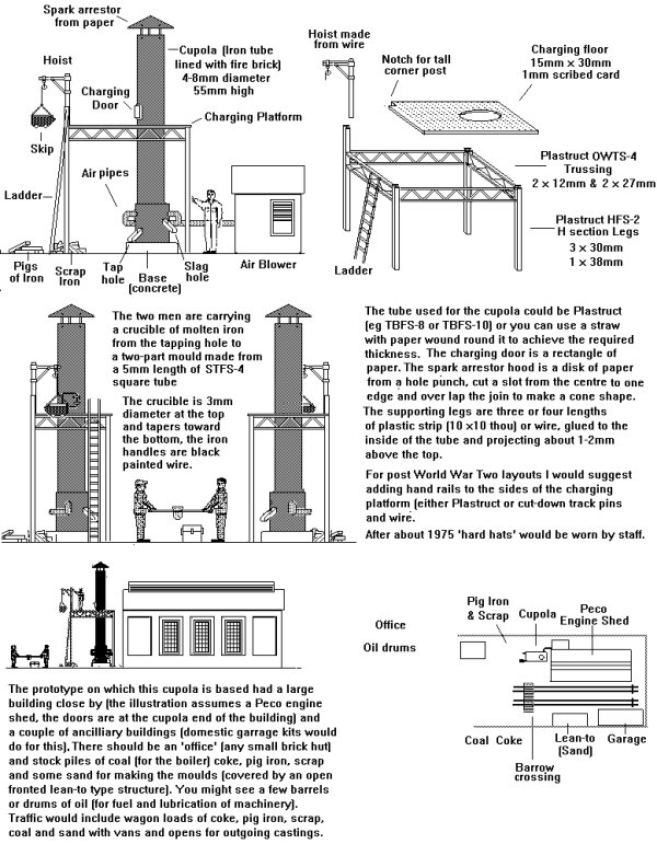
The very early cupola furnaces were small, typically three feet in diameter by about ten feet high with a wooden platform about eight feet square about five feet up the central pipe, the cupola described in Fig ___ dates from the mid nineteenth century, similar furnaces were still operating into the 1950's. The works where wrought iron was produced was commonly called a 'finery' but the foundries soon adopted the basic technique. Wrought iron was quite a common material up to the 1930's but it has now been superseded by mild steel (discussed below) for most purposes.
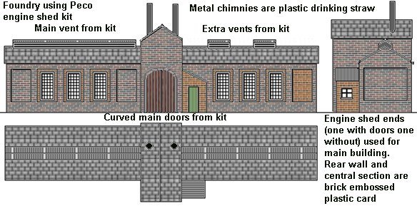
The larger foundry building sketched below was part of an engineering works, the sketch assumes you will be using the Peco engine shed kit for most of the parts, this comes with an extra set of curved-top main doors and two small roof vents.
Fig ___ larger foundry building
I believe in Britain the cupolas were phased out in the later 1970s, replaced by electric induction furnaces (similar in principle to but much larger than the example in the photograph below). The sand used in casting is black (when new it is sand coloured, it is actually a mix of sand with 2-5 percent bentonite clay and about 1-2 percent water, it is re-used and turns black), there is always a ready supply of this, stored under cover somewhere on the site often with a rectangular fine wire mesh sieve about three feet square on a two wheeled trolley used to filter out any scraps of metal when returning it to the pile between jobs. On the main floor of the foundry there will be many of the small pouring crucibles and several sets of handling irons for these.
Incoming cargo would depend on the type of foundry, for those producing cast iron there would be loads of pig iron and scrap metal, the occasional load of sand, regular shipments of coal and (where a gas heated oven was in use) coke for the producer gas plant.
Outgoing cargo could include all manner of cast metal goods, from baths (made from medicine 'bubble packs') to lamp standards (Ratio kits or home-made) and all manner of smaller items (many of which would be shipped in wooden cases and crates although less valuable goods were shipped loose in open wagons, usually in a bed of straw or bracken).
Small foundry operating in 2007
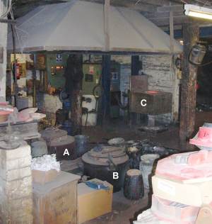
The photographs below were taken at a local foundry (Derbyshire Castings on Churchill Road in Broadheath near Altrincham). This firm specialises in small castings and so does not employ a cupola, instead they melt the materials in the crucible using oil fired, gas fired or electric induction ovens. The gas (A) and oil fired (B) ovens are set into a rectangular hole in the ground, the electric induction ovens (C) stand above ground.
Fig ___ Ovens in a small foundry
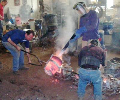
In the photographs below the induction oven is being used to melt aluminium alloy, this is then lifted out and placed on the floor where a man with a metal bar scoops out the slag floating on the top. Additional materials were then added and the crucible was stirred before emptying into the moulds (with a third man using the metal bar to control the residual slag). These scenes could be glimpsed through the large doors of the foundry, adding a red LED with a fibre optic feed to the crucible would add to the scene.
Fig ___ Testing the temperature with a pyrometer
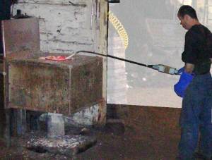
Fig ___ Lifting the crucible of molten metal from the oven
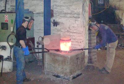
Fig ___ Clearing off the slag from the surface
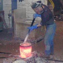
Fig ___ Pouring the molten metal into a mould
Forges and steel pressing
Wrought iron (and steel) can be formed to shape by heating it and belting it with a hammer or pressing it over a former, this heating and forming with hammers and presses is called forging. A forge consists of a solid base and a hammer, a blacksmith's forge had the anvil and the blacksmith used a hand held hammer. The early 'industrial' forges used water-power to drive the hammer, steam powered hammers were invented in Britain in 1839 by James Naysmith (1808-1890) and further developed in France in 1842.
Working with wrought iron, which has a distinct 'grain', meant that the blacksmith needed to know what he was doing if the part he made was to withstand the working stress for which it was designed (for example when making rings to be added to the end of tie-rods). To attach the ring to the end of the rod both are heated to bright red heat, brought together and given a gentle thump to weld the joint. For more on welding see also Lineside Industries - Industrial and agricultural vehicles and equipment.
Given steam power it is possible to heat metal until it is plastic (that is it will flow under pressure) and punch it into a mould, this is known as die forging. Goods produced in this way are likely to be more accurate than those beaten to shape by the blacksmith, although the cost of the plant meant it was only used in large factories. There are two additonal advantages to this method, firstly the raw material needs little or no preparation, a lump or rod can be used as it flows into the mould, and secondly whereas the blacksmith is a skilled man the drop-forge operator can be pretty much unskilled, with a single skilled foreman watching over several operations at once.
To manufacture very long items such as railway lines forging is generally impractical and a system of rollers is used - See also Lineside Industries - Rolling Mills, Wire Drawing and Pipe Works for details on rolling strips and bars of wrought iron and steel.
In 1861 the British developed the hydraulic press which was strong enough to force iron sheets to shape, allowing the development of a range of new products. By the 1870's iron production had peaked and the wrought iron industry went into decline as steel began to become the more significant material. Pressed steel was used in limited applications until the 1930s, thereafter it became much more widely employed (during the Second World War quite a few weapons, notably machine pistols, were made primarily from simple steel pressings for both economy and speed of production). The 'rolled steel drum' was in use in the 1920s. this is made from a strip of steel into which ribs are pressed, lengths are then cut off and formed into a tube and ends added. Probably the most important industrial application of this technology has been the production of car body parts. The two largest body panel firms were Pressed Steel Ltd of Oxford (close by the Morris factory at Cowley) and Fisher & Ludlow of Birmingham and Tile Hill (close by the Standard Motor Co works at Canley) but other, smaller, firms existed, notably Mullins of Birmingham (absorbed by Standard Motor Co in the 1950's) and Briggs Motor Bodies. By the later 1920's the body makers had mostly been bought by the motor car firms but they retained their original factories, necessitating the transport of bodies to the car factories.
^
Go to top of page