Iron and Steel Works
and Stockholders
Recovering metals from ore is called smelting, this is usually done by heating the ore to the melting point of the metal in a blast furnace. This drives off some of the impurities and others burn in the furnace to form gasses, meanwhile the required metal melts and this can be separated from other molten materials (slag) by settling them out.
As shipping the low value ore is relatively more expensive than moving the high value pure metal the smelting areas were in the main located close by the mines. There were exceptions however, the South Wales tin plate and copper smelting firms had plentiful supplies of good quality coal close to hand and used ore carried cheaply by sea from Cornwall.
Also in some cases the local industry was sufficiently strong to justify the movement of ore or partially refined metal when the local supplies ran out. A good example of the latter is the carriage of pig iron from Cleveland to the iron works in Staffordshire and Shropshire in the later nineteenth century to allow these works to continue working when their own deposits had been worked out.
General History of the Iron and Steel making process
Iron is probably the most important metal known to man, without it life as we know it today could not exist. Although other metals are used in considerable quantity, notably aluminium, copper, tin, lead and zinc, iron is still the most important. Iron possesses magnetic properties which allowed the development of electrical power.
Both iron and steel are the same material but in the latter more of the impurities (mainly carbon) are removed. The British Industrial Revolution, the first in the world, was based on iron, the rest of the world industrialised later and based their machines on steel.
Many of the processes involved in smelting iron and making steel required chambers lined with heat resistant bricks. Although heat resistant these bricks are not heat proof and they had to be replaced at intervals (a dirty job by all accounts), hence wagon loads of bricks would be a feature of both iron and steel works.
The fire bricks are XXX in colour.
XXX More on fire bricks XXX
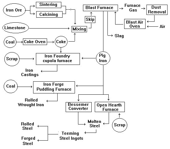
Fig ___ Iron & Steel Making Flow Diagram
Iron was discovered thousands of years ago but early extraction methods relied on charcoal made from wood which was time consuming, expensive and only available in small quantities. Up to 1709 charcoal was used as a fuel for the blast furnaces which separate the iron from the oxygen and other impurities.
Abraham Darby then developed the use of coke in place of charcoal, he did not protect the process with patents and this allowed the rapid development of the iron industry. In Darby's time British iron production was running at 17,000 tons a year, by the 1950's it was up to over fifteen million tons a year. The 'pig iron' produced in the blast furnace has a high carbon content and cannot practically be used for very much. if however it is re-melted more impurities can be removed. This re-melting is usually done in a small scale blast furnace called a 'cupola furnace' (invented in the 1790's by a British ironmaster called John Wilkinson). Scrap metal can be recycled in this furnace along with the pig iron. The molten iron which comes out of a cupola furnace flows well and can be used to make solid castings, it is called 'cast iron'. Cast iron contains a lot of carbon and tends to be brittle, it serves well under compression but is poor when placed under tension. Places which take in pig iron to make cast iron are called 'foundries', you would normally have a foundry associated with an iron works but there were also small establishments catering to local industry (most towns had at least two small foundries) and larger engineering works often had their own foundry on-site.
Pig iron can be used to make cast iron goods in a foundry (see also Lineside Industries - Scrap metal yards, Foundries and Forges) but this material, although resistant to rusting and strong under compression, is brittle and cannot be re-heated and shaped. Cast iron is still widely used today (motor car engine blocks are made of cast iron).
If you remove nearly all the carbon from pig iron or cast iron you get 'wrought iron' (sometimes called 'malleable iron' in older texts) which contains less than 0.1% carbon and about 3% 'slag'. Wrought iron is much stronger under tension than cast iron and the slag forms a coating or skin on the surface which imparts certain qualities to the metal, notably corrosion resistance. Wrought iron can be hammered into shape when red hot so places where wrought iron was made are usually called 'forges' (a forge is a hammer and an anvil). Originally wrought iron was made by beating bars of red hot cast iron and beating it to de-form it and allow the air to get at more of the carbon (which then burns away). This was done in a works known as a 'finery'.
In 1784 an iron works owner by the name of Henry Cort obtained a patent for producing wrought iron in bulk by stirring molten iron in a reverbatory furnace (a process known as 'puddling', for a description of a reverbatory furnace see Lineside Industries - Prototype industrial ancillary structures). What happens is that the air would oxidise and remove some of the remaining carbon (becoming CO2 gas) producing low carbon wrought iron. Mr Cort also developed and patented a hot rolling process for iron heated until it was the consistency of a thick paste and then passed between powered rollers in a rolling mill which produced better quality iron much faster. The combination of these two developments allowed his works to produce about fifteen times as much iron in a given time and with a given amount of fuel. Cort's business partner was then prosecuted for fraud and (as he was a full partner) Cort was also held responsible and his patents (both for the puddling furnace and his wrought iron rolling mills) were confiscated and thrown open to all manufacturers, the result was a massive increase in wrought iron production. The combination of cast and wrought iron along with Mr Cort's rolling mill allowed the industrial revolution to mechanise production but by the 1870's iron production had peaked and the industry went into slow decline as steel began to become the more significant material.
Cort's puddling process was further improved in 1816 when Joseph Hall of Tipton developed an oxygen rich lining for the puddling furnace (this was called 'wet puddling' to differentiate it from Cort's system which in turn became known as 'dry puddling'). A small quantity of haematite ore is added to the pigs of iron in the cupola at the foundry. The oxygen in the haematite (Fe3O2) combines with most of the carbon in the pig iron to form carbon dioxide and the resulting iron has less than 0.1% carbon in it.
Wrought iron can be heated and rolled into long strips or sheets. The first sheet rolling mill was built in Wales in about 1720 but machines for cutting hand made sheets into strips had been in use since the sixteenth century. Henry Cort's iron rolling mills using grooved rollers which produced bars of standard thickness represented a major advance.
Wrought iron can also be formed to shape by beating it and belting it with a hammer or pressing it over a former. This heating and forming with hammers and presses is called forging. A forge consists of a solid base and a hammer, a blacksmith's forge had the anvil and the blacksmith used a hand held hammer. The early 'industrial' forges used water-power to drive the hammer, steam powered hammers were invented in Britain in 1839 by James Naysmith (1808-1890) and further developed in France in 1842. Wrought iron was formed in the forge to make bridge parts, sections for ship building and railway lines. In 1861 the British developed the hydraulic press which was strong enough to force iron sheets to shape.
Steel is iron with all the carbon removed and a little added back in, this produces something chemically similar to wrought iron but with a different crystalline structure. Up to the middle of the nineteenth century it was made in small pots (called 'crucible steel') and prices reflected the small scale and labour intensive manufacture. By the 1850's Britain was producing several million tons of iron in various forms every year but only a little steel. Things changed in the mid 1850's when Henry Bessemer invented his 'converter' in which air is blown through molten iron, the oxygen in the air burns away the carbon to produce very pure wrought iron. To clear away the oxygen dissolved in the molten metal and restore the required amount of carbon to make steel a little ferro-manganese (an alloy of iron, manganese and carbon) is then added. The manganese combines with any free oxygen whilst the carbon combines with the iron to make steel. The steel is teemed (poured into moulds) to form ingots which are then re-heated to enable them to be rolled or hammered into shape.
Bessemer's converter was a major breakthrough but it could only be used with very pure ores, most of which had to be imported from Spain and Sweden. Much of the iron ore in Britain (and in the rest of the world) is tainted with phosphorous and although it made good iron it could not be used for making steel. In 1876 Sidney Gilchrist Thomas working with his cousin discovered that he could line the Bessemer vessel or open hearth with crushed dolomite (MgOCaO), which reacts with and removes the phosphouous producing a phosphate slag which had the additional benefit of being a valuable fertiliser ('Basic Slag').
The next big development was the Siemens-Martin or open hearth process of 1866, using the reverbatory regenerative furnace invented by Frederick Siemens (1826-1904) in 1856. The regenerative furnace uses the waste heat generated to pre-heat incoming air instead of simply blowing it out of the top as in the Bessemer system. The re-use of the heat allows pigs of cold iron to be used to charge the furnace instead of the molten iron of the Bessemer system. To make 100 tons of steel in the open hearth system requires up to fifteen hours of careful work as opposed to about twenty minutes in the Bessemer converter. The open hearth process requires a lot more skill on the part of the operators, but it is a lot cheaper due to the re-use of the heat. The Bessemer system remained in use up to about 1925, rapidly decreasing in use after the First World War, and thereafter the Siemens open hearth method became the standard method for steel production world wide until the late 1950's.
In 1863 Henry Clifton Sorby (1826-1908) working in Sheffield discovered the microstructure of steel and founded modern metallurgical science. Steel gradually replaced wrought iron for most applications although wrought iron production peaked long after the development of steel and remained significant up to the 1930's. There was a puddling furnace producing wrought iron at the Butterly Ironworks which remained in use until 1965 (no better way of making wrought iron having been found). Cast iron's particular properties mean that it remains in use today.
The Basic Oxygen Process for making steel was developed in Austria in about 1950, and this system has turn largely replaced the open hearth system. The Basic Oxygen Process uses pure oxygen in large quantities (called 'tonnage oxygen') which is blown into the liquid metal to combine with the carbon and remove it (lime can also be injected to reduce the phosphorous content). The oxygen used for this system is usually made on site but when the on-site equipment is being serviced oxygen is delivered in British Oxygen Company liveried cryogenic (low temperature) railway tank wagons.
There is one other option for making steel, the electric furnace process, which offers the possibility of turning the heat up or down and thus controlling directly the creation of the steel. It costs a lot to make steel in this way so the technique is only used for making high grade alloy steels such as stainless steels and steel used for cutting tools.
By 1968 technology had improved to the point where molten steel could be poured into the top of a water cooled mould and drawn out as a continuous bar at the bottom. This technology was soon adopted in most of the worlds major steel works.
British Iron & Steel Industry
Although at the forefront of the early European iron industry Britain soon began to fall behind. By the 1890's American iron production was greater than Britain's, in 1904 Germany pulled ahead and the General Strike of 1926 pushed Britain into fourth place behind France. The main reason British iron and steel industry fell behind the international competition was that it remained a fragmented collection of relatively small scale businesses. The USA, France and Germany were all embarking on their own industrial revolutions, their iron and steel firms were soon in fierce international competition which they fought by forming conglomerates and cartels. The Americans such as Andrew Carnegie (United States Steel Corporation) and the German industrial cartels had the advantages of the economies of scale and were better able to weather the dips in demand than the smaller British firms. Between 1870 and 1913 British coal production fell by about fifty tons per man per year and prices rose, this was the reverse of the situation in America and adversely affected the British iron industries competitiveness.
It is in the nature of the business that when times are good everyone wants steel, but even a slight fall in industrial growth has a disproportionately damaging effect on the iron and steel industry. Foreign producers were protected by tariff systems whereas the British were not, this meant that during lean times there was considerable 'dumping' of foreign steel in Britain.
By the time the of the First World War the industry was not healthy and was ill prepared to meet the sudden increase in demand. Many of the smaller firms had to amalgamate to allow for investment in new plant but when the war ended the industry found itself with a considerable over capacity and with much of its manufacturing facilities poorly located. There was a brief post war boom but the slump in demand hit in the 1920's and lasted a decade. Many of the several hundred smaller firms failed and were taken over by banks. Unemployment amongst steel workers seldom dropped below thirty percent during this period.
There was considerable pressure to nationalise the industry, starting in the early 1930's but things picked up again in the later part of that decade. In 1932 the government set up an organisation to support the industry (which was represented by the British Iron and Steel Federation) and in 1937 an organisation called BISC (the British Iron & Steel Control (Ore) Ltd.) was formed to distribute home produced ores (mainly from the Lincolnshire ore fields). This organisation operated a fleet of ore hopper wagons in its own livery.
The Second World War saw a different pattern of development from the First, for one thing a degree of rationalisation had already occurred within the industry and the industry's own co-ordinating body (BISF) was able to change to a war footing. In this war the industry concentrated on building specialist mills for processing steel imported as billets from America, which meant the post war problems of poor location and over capacity were largely avoided.
Nationalisation came with the post war labour government in 1948, however the Conservatives de-nationalised the industry following their victory in the 1951 election. Neither course of action resolved the continuing problems in the industry and after much debate a revised form of nationalisation of a large part of the industry (including the fourteen largest plants in the country) occurred in 1967 with the formation of the British Steel Corporation. By 1973 the British Steel Corporation was again making a profit.
Fig ___ British Steel logo

British ore suffers from high levels of impurities, it has only a small amount of iron in it and consequently requires more coke for processing. Imported ore although more expensive has a greater yield of iron and uses less coke so it is less dependant on the cost of coal. As a result, particularly since the 1950's, there has been a shift of major manufacturing away from domestic sources of coal and ore (mainly in the Midlands) toward coastal sites.
British Steel concentrated production in four areas, Glasgow (Ravenscraig), Middlesborough on the North East Coast, Sheffield and Scunthorpe in the North East Midlands and Port Talbot & Llanwern in South Wales. The facilities at Ravenscraig and Llanwern were developed from existing privately owned works in the late 1950's and largely duplicated each other. Ravenscraig was partly funded by the government who wanted it to supply steel to the then booming ship building industries of the Clyde and Northern Ireland. The plant was operated by a company called Colvilles, who were very dubious about the plants viability in the long term. These worries proved well founded and the plant was finally closed down in 1992.
Not all firms were taken into British Steel, smaller firms continued to operate on most of the coalfields such as those around Liverpool and Manchester (Lancashire Steel Corporation), and the belt between Wolverhampton and Kettering. The steel making industry at Barrow was supported by its shipbuilding industry (although by the 1960's it was loosing money) and Workington in the far North West also had a steel industry. Most of these firms fell by the wayside in the face of the glut of steel on the worlds markets, the massive steel plant at Consett closed in 1980 and the big Stewarts & Lloyds steel works at Corby (set up in the early 1930s) closed down in the early 1980's.
Sheffield has developed a specialised industry producing unusual high quality steels and alloys. The barrel of the British L1A1 tank gun (the most widely used tank armament in the West) is made from 'electro-slag refined' steel produced using a process developed in Sheffield in the 1950's. Although the scale of the industry in Sheffield in today (later 1980s) much reduced it remains the centre for British high technology steelmaking.
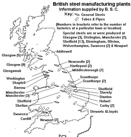
Fig ___ Iron And Steel Works In Britain
British Steel was privatised in 1988 to become British Steel Plc and merged with Dutch firm Koninklijke Hoogovens to form Corus in 2000. On April 2 2007, Corus became a subsidiary of the Indian owned Tata Steel.
Modelling an Iron or Steel Works
Note - Rolling mills are discussed in more detail in Lineside Industries -Rolling Mills, Wire Drawing and Pipe Works, forges and foundries are discussed in more detail in Linside Industries - Scrap metal Yards, Foundries and Forges. Iron and steel wholesale distributors or 'Stockholders' are discussed later in theis section. Modelling the various iron and steel products and their associated rolling stock is discussed in the section on Wagon Loads & Materials Handling - Wagon Loads - Metals.
An iron or steel works is a big enterprise, in practice most layouts represent this kind of industry by having some large metal sheds on a set of sidings, the remainder of the works being on the backscene. These works were dirty and dark, no lighting was used because the material being worked was glowing, everything was rusty and streaked with black soot. Since the later 1990s a number of kits have become available allowing a more thorough representation to be built and there are now a few layouts set entirely within the confines of the works with the rest of the railway represented by a fiddle yard.
The blast furnace consists of a large oven built to withstand high temperatures and supplied with air under pressure, the ore and fuel are placed inside and set alight, melting the metal ores and separating them from the rock they were found in. The blast furnace was introduced into Britain in the fifteenth century and up to the early eighteenth century these were fuelled with charcoal. The iron these furnaces produced was good enough to build the first steam engines in about 1712. By the early sixteenth century the area in the South of England known as the Weald was the main centre of production using the charcoal method but there were groups of charcoal fired blast furnaces in the Forest of Dean, South and North Wales, the West Midlands, Derbyshire, Yorkshire, Furness and the North Staffordshire-Cheshire border.
As noted under Mines the most common ore in Britain is Spathic ore mixed with clay, called 'ironstone'. To recover the iron the ironstone is first roasted by mixing it with a little coal or coke and burning it in small heaps or shallow kilns (this is sometimes done at the mine site as illustrated in Fig ___). This drives off the water, sulphur, arsenic and some carbon dioxide. The resulting partly purified ore is then put in a blast furnace with coke and limestone and set alight. Pre-heated air is blown in through the bottom (the inlet pipes for this air are called tuyeres).
The coke burns to form carbon dioxide gas and heats the mix up to about fifteen hundred degrees centigrade. The limestone and ore melt and the super hot carbon dioxide de-composes the limestone (calcium carbonate), the calcium combines with the residual sand in the now molten ore to form calcium silicate, the iron sinks to the bottom, the calcium silicate floats on top as a 'slag'. The slag is tapped of and sold for road making and for use as a fertiliser. The iron and slag are tapped off at intervals of a few hours and the whole thing is kept going twenty four hours a day for years, until the brick lining requires replacement. This produces a lot of soot and smoke, the south of Staffordshire became known as 'the Black Country' (red by night, black by day) following the development of the iron works there in the eighteenth century.
The molten iron tapped from the blast furnace can be flowed into sand moulds where it forms blocks called 'pigs' (said to be named after the similarity of the row of moulds to a row of piglets feeding on mum). More recently a chain of metal moulds has been used, carrying the iron under a water spray to cool it and tipping out the 'pigs' at one end. In many works the liquid iron is moved for further processing in crucible wagons similar to the slag wagon shown above.
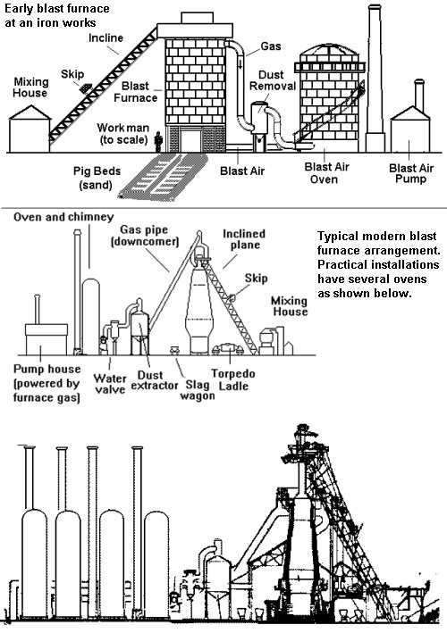
Fig ___ Blast furnaces
The molten metal was transported to the moulds in a large steel ladle, containing many tons, suspended from a gantry crane. One of the foundries at the Patricroft steel works near Manchester had a three inch thick solid steel floor as the man driving the crane had an epileptic fit and emptied the contents onto the foundry floor. This melted the bottom of the access stairs to the gantry and the fire brigade had to bring in several engines to spray water on the steel to cool it sufficiently for a rescue team to get a ladder in and rescue the unfortunate crane driver.
Pigs of iron are typically about three foot (1m) long, four or six inches (10-15cm) wide and about three inches (7.5cm) thick, as the SG of iron is 7.87 so these would weigh in at about 123 lbs (56Kg) which is about 20 per ton. The pigs could be any size required but if they were much larger they would require mechanical handling and the quoted size is based on a number of illustrations.
Pig iron has little practical value as it contains too many impurities, making it very brittle, for most jobs the iron had to be further processed into 'cast iron' at a foundry. The railways provided 'pig iron' wagons to deliver pigs to foundries, generally these had low sides and reinforced ends to avoid the pigs breaking through when the wagon was shunted. BR built some wooden five plank wagons with steel sections replacing the bottom two planks at the ends.
Fig ___ Sketch of an 1860's blast furnace with suggested layout
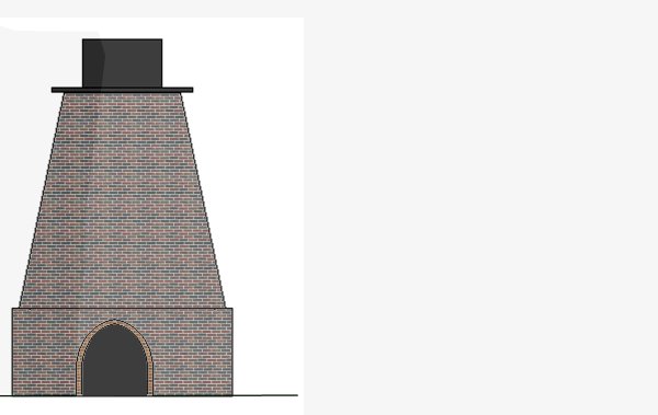
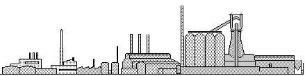
Fig ___ Basic iron works for painting on the back-scene
Steel Works
Steel works are similar to iron works but with an additional stage of processing as shown on the flow diagram above. Any steel works will therefore include a blast furnace, its design depending on the date of your layout. There are many kinds of steel, the two main categories are carbon steel and alloy steel. The carbon steels are the most widely used and the characteristics vary depending upon the amount of carbon they contain. Low (less than 0.7% carbon), Mild (0.1 to 0.25% carbon), Medium (0.2 to 0.5% carbon and high (0.5 to 1.4% carbon) Low carbon steels are called soft and these are used for wire sheet metal and rivets, high carbon steels are called hard and they are used for springs, hammers and chisels.
Alloy steels are used for specialised applications, stainless steel contains about 14% chromium and usually has some nickel in it as well, it was discovered by Harry Braille of Sheffield in 1913. The firm he was working for was trying a range of alloys and after testing the ingots were piled up as scrap. He noticed that some of the ingots they had experimented on did not rust but remained shiny. Manganese steel is used for the teeth of excavators and other tough jobs, made from iron ore which contains the material.
From a modeling point of view a steel works would simply be too large to contemplate as an adjunct to a layout and a better alternative would be a set of 'exchange sidings' where the railway connected with the internal rail system of the works. Many of these works had extensive internal railway systems however and such a works would make the basis for an interesting industrial layout. Lima used to offer a bogie 'torpedo ladle', these had a cylindrical centre section, lined in concrete, with motors at either end which could rotate the drum to empty it. Once filled they had to remain hot as if they ever cooled they would crack. These wagons carried the molten metal from the blast furnaces to the foundries and operated only within the steel works (although you could have one or more being delivered by rail to the works).
There are several structures which identify an iron or steel works and many of these were large enough to serve painted on the backscene. The main structure is of course the massive blast furnace (typically a hundred feet or more high) but steel works often process coal to make coke on-site, using the resulting coal gas to fuel various processes.
Coking plant and gas holders were therefore a common feature of steel works but the gas holders in more modern works are of the waterless type and resemble oil tanks rather than the more well known telescopic gas-works type. The company name was sometimes painted on the side of the gas holder (the steel works at Ravenscraig had these 'oil-tank' gas holders with the British Steel Logo and RAVENSCRAIG on the side in lettering about ten feet high).
Fig ___ Steelworks structures for a back-scene
Steel works traffic
Incoming cargo would include block trains of ore, pig iron and scrap metal, sand (for casting moulds), limestone, coal (and possibly coke) as well as wagon loads of more exotic materials such as private owner wagons carrying lime, tankers of ferric chloride and wagons carrying carboys or tank wagon loads of acids.
British Steel commissioned some 102 ton GLW bogie tippler wagons for feeding raw materials from the docks to its Welsh steel works in the late 1970s, a typical make up for this working in the early 1980's was twenty of the wagons pulled by a pair of class 56 locos. With the fall in demand some of these have been used for carrying scrap.
Outgoing would be iron pigs or steel ingots and castings, possibly coke (after the mid 1970's when the gas works closed down) and possibly all the other products normally associated with gas works (see Gas Works for further information). Long products are so called because they come off the mill as long bars of steel, this includes various forms of girder with cross-sections shaped like an H or I (called joists, beams and columns), a U (channels) or a T. These types of steel 'section' are used for construction. Bars can have cross-sections the shape of squares, rectangles, circles, hexagons, angles. These bars can also be used for construction, but many types of bar are also used for engineering purposes. Rod is coiled up after use and is used for drawing into wire or for fabricating into products used to reinforce concrete buildings, as are some types of bar.
A lot of products are finished at the steel works but some traffic is in 'semi finished products', generally in the form of ingots or large bars of steel being shipped for further processing. Steel ingots fall into several basic sizes called billets, blooms and slabs.
Billets and blooms are used to make what are called 'long products' such as girders or wire. A billet is a long ingot, typically six inches square and as long as the available rolling stock can carry, Slaters 40x40 thou microstrip is about right for this material. They are used in making wire or rolled flat to make small sheets (which may in turn be used for making pipes). Billets for forming into thick plate are generally about twenty five tons and those used for making wire, small strip and small bars are typically only about six tons in weight.
Blooms are large raw steel ingots being shipped for further processing, this is really a post World War Two development as earlier all the work required would be one at a single iron or steel works. Blooms weigh in at abut thirty tons, they are typically about a foot thick by two foot six wide and about twenty foot long. Blooms are often loaded 'hot' onto wagons and the stock used usually has raised bolsters to allow cooling air to circulate. A slab is a large oblong section length of steel and again they are a modern development.
Slabs are big, perhaps eighteen inches thick by a couple of foot wide by twenty foot long. Slabs up to about thirty tons are sent to rolling mills for forming into rails, girders and (mainly) plates. Plate is a large, flat piece of steel perhaps 10mm or 20mm thick (although it can be up to 50mm thick) and up to 5 metres wide. It is used for example to make the hulls and decks of ships or to make large tanks and boilers. It can also be rolled up and welded to form a large steel tube, used for oil and gas pipelines.
Slabs are also used to make steel strip, normally called hot rolled coil, made by passing the hot slab through a series of rollers before being coiled and allowed to cool. Railways referred to this as 'stripcoil' and build or modified a number of wagons for this traffic from the early 1950s on. Hot rolled coil is a lot thinner than plate, typically a few millimetres thick, although it can be as thin as 1mm. Its width can vary from 150mm to nearly 2 metres. It frequently goes through further stages of processing such as cold rolling and is also used to make tubes (smaller tubes than those made from plate). In the 1980's quite a lot of slabs were exported to be rolled into long strips of steel sheet and the resulting coiled strips were then sent back to Britain.
Modelling the various steel products and their associated rolling stock is discussed in the section on Wagon Loads & Materials Handling - Wagon Loads - Metals.
Iron & Steel Works Internal Railway Stock
Iron and steel works often featured their own internal railway system with their own wagons. These were not always standard gauge however in 'N' the easiest option is to use RTR standard gauge models and parts.
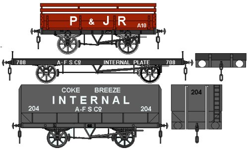
The sketch below shows a non-convertible coke wagon is an internal user vehicle from an iron works in the north east, the livery dates from between the two world wars. You could use the livery on a standard Peco wagon fitted with Peco coke rails but to make the thing a little different you can produce a fairly accurate wagon by cutting away the sides of a Peco 5-plank mineral wagon kit leaving the side corner plates in place. Now reduce the height of the ends slightly, fit new sides from scribed 30 thou card and add a set of Peco coke rails.
The plate wagon could be modelled from the Peco kit, I would suggest using the fifteen foot brake van chassis with the foot boards removed. The livery shown is taken from photographs in Peter Mathews' book on PO wagons (see bibliography).
The large coke hopper wagon shows a typical livery used for internal use only at a steel works from the 1960s to the 1980s (possibly longer).
Fig ___ Internal User Stock
As part of the processing of the iron or steel the internal railway system was also required to carry various hot materials about the site. This required purpose built wagons, the sketch below shows a selection which could be used for 'set dressing' when the works proper is mainly confined to the backscene.
The simple metal box on wheels was used to move hot ingots from place to place and also as a barrier wagon to separate hot slag wagons from the locomotive and from each other. This is a simple proposition if you have any old Lima chassis in your bits box, just sand the sides a little to reduce the level of detail then add a strip of postcard folded to form a flat top and sides. Technically it should have solid ends as shown but that gets difficult with N Gauge couplers.
The short wagon with the metal shield at one end is a 'coupling wagon'. Specialised vehicles had American style 'buckeye' couplers (similar to the Kadee N Gauge coupler) and coupling wagons were used to allow locomotives with standard couplings to handle these vehicles. The best bet here would be to cut a section from the centre of a spare Lima chassis then add the top, sides and end-plate from card (plastic or post).
The simple wagon, coupling wagon and the slag wagon are based on illustrations in an article by John Allinson on his O Gauge Oval Ash B layout, which represents part of the internal railway of the former Round Oak steel works. The article was published in Your Model Railway magazine, September 1986. For the present purposes it is assumed that the slag wagon model would probably serve as 'set dressing', parked on a siding and not expected to move. Hence some compromise has been adopted to ease the modelling.
The slag crucible is cut from the end of an Olbas Oil or Vicks inhaler cap and the chassis is made using 20 thou card. The chassis consists of two side members with recesses for the wheels, these are held the correct distance apart by adding the end plates (X) and top plates (X). When dry add the wheels then fit the flat plates above the wheels (X).
The crucible needs a rim round the top edge, 10x10 thou strip will do or you could use thread glued with Uhu or similar glue. There are lifting lugs on the sides, I suggest these are most easily represented using two lengths of 10x20 thou as shown. The crucible has a pivot bar on each side (X) and on the wagon this is supported by two 1mm lengths of 1mm diameter rod (X) mounted on a shaped scrap of 20 thou card (X). The solid wheels can be any you have in your bits box, for example you may have some old Lima chassis if you have transferred the bodies onto Peco chassis. Peco wheels would do equally well but in either case you will need to cut or file the pointed bearings of the wheels flat. The wheels are visible so for Lima wheels paint the flanges 'track' colour to tone them down, for the Peco wheels paint the tyres silver.
One small point is that the slag wagons weighed in at around thirty tons, so they were moved about in short rakes. This was not a problem as four wagons would be enough to deal with one tapping of the slag from the furnace. The slag was molten and was taken to a raised bank to be tipped, if something went wrong the whole lot set solid and the slag wagons themselves would sometimes warp with the heat. One option then was to just push the wagons off the track and down the bank.
Fig ___ Specialised Internal User wagons for Iron & Steel Works
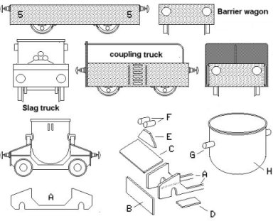
Also sketched is a slag wagon drawn from a photograph of a vehicle in a steel works at Scunthorpe. This has a flat-sided tapered crucible, slightly longer than it is wide and with rounded corners. The chassis is an alternative shape which could be used with the crucible described above.
Stockholders
Stockholders take in the plate, girders, angle, tube and (since about 1950) strip-coil from the iron and steel works and sell this to their local industries, cutting the material down to manageable sizes where required. One advantage of this industry in the present context is that goods in often looked remarkably like the goods shipped out, reducing the need for wagon load adding and removal.
A notable exception to this is strip coil, this would be the inward cargo, going out would be sections of plate cut from the long strip. As an example Philip Holmes was able to advise that a local firm in Manchester in the 1980s regularly took in coils of 0.5 inch and 0.74 inch strip coil steel and guillotined this down to produce strips 9 inches wide 15 inches long to be used as the wheel rims for 'Bobcat' mini-cranes. The strips were steel12 at a time. These sets were then stacked with strips of timber between them and re-banded to produce a block, the timber strips providing access for the prong of a fork lift truck.
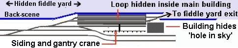
A related problem regarding the appearance of loads on wagons is that the services offered tended to be cutting (sawing or guillotining) as well as shot-blasting and painting (or coating), hence plates and girders and particularly tubes might arrive looking rather battered and rusty but would often leave looking smooth and with a coating or reddish brown primer. One solution is to route the sidings into a hidden loop connected to the fiddle yard, allowing 'full' and 'empty' trains to traverse the layout in the appropriate directions.
Fig___ Hidden loops for a stockholders yard
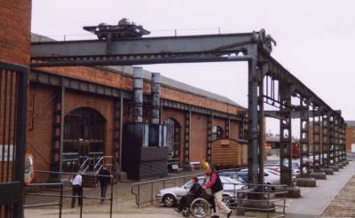
Given the nature of the work a characteristic feature of a stockholders yard was a selection of cranes, fixed and mobile. In the context of a model railway the establishment could be represented by an open-sided shed on the backscene (this requires an inch or two of depth to allow the stacked metal to be shown inside), faced by a yard with inset railway tracks and a gantry crane. The example shown below is at a former goods yard (built in the 1830s and closed in 1975), it was for a time an engineering works and is now part of the Manchester Museum of Science and Industry, this example is actually rather narrow for a stockholders yard but would be acceptable for a small firm on the fringe of a town.
Fig___ Large gantry crane suitable for a small stockholders yard
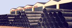
Tube and hollow section steels have often been a specialist area for stockholders, the only difficulty is cutting the required number of tube sections dead square and to the same length for the stacks in the yard. In N steel tube is very thin, hence you can cut Plastruct tube more or less to length then add a paper wrapper extending beyond the end of the plastic to give the required wall thickness to the tubes. As is is a lot easier to cut strips of paper to length you end up with better looking pipes.
Fig___ Steel tubes stores in a stockholders yard
The stock range of a stockholders tends to be diverse and might include 'Merchant Bar' (Rounds/Squares, flats, Tees, Angles and Channels), 'Construction Steel' (Universal Beams and Universal Columns - Some stocked with a primer painted finish), 'Sheet Stock' (Hot Rolled Sheet and Plate, Cold Reduced Sheet, Galvanised Sheet, Floor Plates (Durbar Pattern), Open Steel Floor Grating and galvanised Weld Mesh), 'Engineering Steels' (Bright Mild - Round, Flat, Hexagon and Angle, Precision Ground Stock and Alloy Steels). Larger yards might also carry 'Hollow Sections' and 'Tube' (including black Gas pipe (modern pipe to BS 1387), as well as Black and Galvanised Electric Resistance Welded Tube & Box section, Seamless Tube - Hot Finished & Cold Drawn) although pipes and tubes tended to be a specialist area. As well as the steel sections they might also carry Elbows and Fittings, End Caps, Pallet Feet, Stair Treads, Handrail Stanchions, Fixings and Consumables.
^
Go to top of page
International Good Guys ~ Making the world a
better place since 1971 ~ Site maintained by

All material Copyright © Mike
Smith 2003 unless otherwise credited