Industrial buildings
Up to the 1940s most towns were a mixture of dwellings and industrial premises, factories would be found on a street corner or even part way along a street of houses, most workers walked to work until comparatively recently. Today we are used to separate residential 'suburbs' strung along railway lines and roads, our towns are now primarily catering for retailing and administration whilst warehousing and industry are confined to out-of-town industrial estates. This separation of industry from residential areas is actually a largely post World War Two development, even today you may well find a small factory only one or two streets back from a main road in a suburban area.
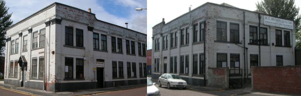
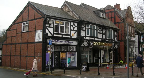
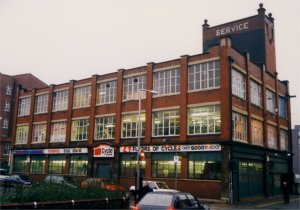
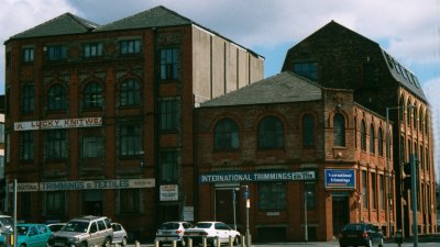
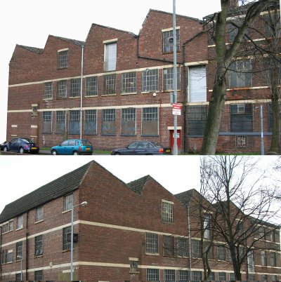
People usually walked to work and a legacy of the early industrial revolution in larger towns and cities were the badly built 'slum' houses surrounding factories. These only began to be replaced after the 1870s when Disraeli supported a series of Acts on housing and public health. From a railway modelling point of view it should be remembered that up to the 1970s a lot of industry was surrounded by housing, so a row of 'house backs' can serve as a back-scene on the line leading to the factory. The separate 'industrial estate' was really a creation of the 1930s, however all the existing factories remained in use (although they might change their purpose from time to time). Factories prior to the 1970s were often designed to look imposing or at the very least tidy, with some expense being devoted to ornamental features in the style of the times. The example below dates from the early 20th century, it is located within half a mile of the local town goods yard.
Fig ___ Factory in a suburban area surrounded by housing.
Most industrial buildings are essentially generic, many if not most factories wewre bought and sold several times, being used for widely different purposes during their life. Where buildings were built to meet the needs of specific industries and supported features that identify the industry concerned, these are considered where relevant under their respective headings. Some distinctive buildings and structures were used in a range of industries and some elements of industrial building design became generally accepted practice.
It is really only since the 1970s that utterly utilitarian shed-like industrial buildings have become the norm, although even these are often modified over time, many have some interesting external features and being built of modern materials of varying quality the weathering effects can sometimes be quite dramatic.
Obviously, as many older factories pre-date the railways, most were not located close enough to employ a direct railway connection or 'private siding', these simply used the local goods yard. A lot depended on the nature of the raw materials being supplied and the proposed market for the goods being manufactured. In any built up area there would be a railway station within a couple of miles, even in more rural areas the station was seldom more than five miles distant and usually less. Having said which once the railways arrived a lot of local industries would cluster around the railway station and a short siding run into one of these was not at all uncommon. Where the goods and materials handled were large or heavy a railway siding would be likely on any premises close to a line.
Rural industries would only warrant a railway connection if they were close enough to a line and large enough to generate sufficient traffic. Hence an iron works would almost certainly be rail connected but a small mine or quarry might rely on road vehicles or a light 'plate-way' or narrow gauge line to connect to the railway proper.
Where a private railway siding was laid into an industrial yard the nature and design of the facilities would be governed by the goods dealt with. Heavy items such as bricks or stone would usually require the provision of a raised loading bank (prior to the introduction of palletised loads), although conveyor belt systems were in common use prior to 1920. Anything likely to be damaged by the weather would be loaded under cover, either in a shed or under an awning covering a loading bay.
Basic Industrial Architecture
The architecture of the humble un-romantic factory, mill or mine has been largely ignored, in spite of the fact that a large proportion of the population have spent between a third and half their life in some form of industrial building. 'Industrial archaeology', the study of industrial architecture and working practices, was considered something of a pass-time and not worth serious consideration. By the time it became accepted as a serious subject in the early 1980s much of the industry it was to study had gone. Even today you can find any number of books on cathedrals, large country houses and rustic cottages, but it is much more difficult to find illustrations of jam factories, brick works, steel works and dairies.
The first factory in the modern sense was probably the mill built of brick with a slate roof on an island in the river Derwent at Derby, erected in 1720. This was the first factory where the pace of work was determined by the speed of the machines rather than by the workers, it even had a bell in a tower to call the work force at fixed times. This ground breaking approach was successful but it was 1771 before Richard Awkwright built his water powered cotton mill, again using brick with a slate roof, marking the real beginning of the change to centralised mass production.
Industrial buildings are built to do a job and this influences their design, the idea the 'function dictates form' became an architectural style in its own right (the Chicago School) in the later nineteenth century. Buildings were erected to house machines or provide storage space, the limitations were in the strength of the materials used and in the building techniques.
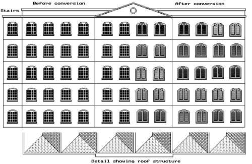
There was a limit to the span a roof could cover and the usual approach with large buildings was to add a series of pitched roofs supported on the tops of the rows of internal iron pillars. This is shown in Fig ___ which depicts a mill converted into a factory.
Early in the nineteenth century there was a great interest in the ruins dating from the medieval period and also in the ruined buildings of ancient Greece and Rome. The former produced the Gothic Revival architectural style, which added heavy ornate decoration to buildings giving them a medieval air. The great voice of the Gothic style was William Ruskin who said, in his book The Seven Lamps of Architecture 'When we build, let us think that we build for ever'. This ethic was reflected in a great deal of Victorian architecture, much of which remains in service today. Most of the Gothic features served no practical purpose and although popular for churches and civic buildings they had little influence on factories and warehouses.
Interest in the Greek and Roman architecture produced what became known as the 'Classical' architectural style with its fondness for rows of stone columns and large carvings. Although mainly associated with large public buildings reflecting civic pride the features of 'classical' styles also found their way into industrial design, reflecting the pride of the factory owners and projecting an air of solid reliability.
Early 'industrial' buildings of the eighteenth and early nineteenth centuries were mainly mills for grinding cereals and for spinning and weaving cloth. These usually had a wooden frame and floors, and with the mix of oil lamps and cotton waste or powdered flour there were many fires. By the early nineteenth century materials such as standard bricks and cast iron structural elements were available and a degree of standardisation of design had been achieved. This meant that the architect no longer had to personally supervise the construction of buildings.
The new materials and techniques allowed the development of 'fire-proof' buildings using iron pillars and solid brick floors supported by brick arches and later concrete floors and roof. Not all buildings were constructed in this way and not all the older buildings were demolished. In the 1960s my father was involved in converting several old mills for use as electronics factories and some of these had wooden floors soaked in cotton oil (according to the fire brigade if they went up they would have taken only half an hour to gut the building completely).
Factories built in towns, or where an earlier factory had prompted the building of workers houses, had to use the spaces left over. Multi-storey buildings typically cost twenty percent less than single storey buildings with the same floor area. As the early machinery used a single steam engine or water wheel the multi-storey factory was quite popular and brick built factory and mill buildings were therefore commonly of the three, four or five storey construction.
The disadvantages lie in production, with the increasing pace of technological development in the twentieth century buildings lasted a lot longer than the machines they were built to house and making changes is difficult in a multi-storey structure with its internal supporting columns.
By the 1930s the most common design for factories was a large ground floor working hall, often as high as a two or three storey building, fronted by a two or three storey office block.
The pre war era saw a number of rather elegant factory buildings with design elements influenced by the Art Nouveau movement.
In the 1960s the word 'modern' achieved totem significance and a lot of rather ugly glass and concrete buildings were erected. the new idea of building planned New Towns had replaced the pre-war 'Garden City' concept but the increasing availability of the motor car encouraged the development of simple 'industrial estates' and building materials had evolved to the point where very large open plan buildings could be erected. There was a brief period in the 1980s when anyone asking an architect to design a large structure got something based on a tent but by the late 1980s the very large tin shed, often with a moulded and sometimes illuminated plastic hoarding outside, had become the norm.
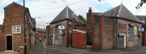
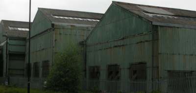
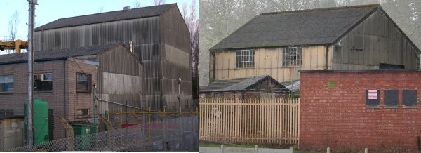
Factories fall into three main types, purpose built buildings, those where a number of buildings have been built as the firm expanded or the nature of the work changed and those housed in buildings originally built for other purposes. Industrial buildings were (in the main) purely functional and not constrained to any great extent by the sensibilities of fashion, as a result many industrial buildings look surprisingly 'unrealistic'. The examples below, part of a small back-street factory in a built up area, are (on the left) a rather narrow two-storey building added along one side of a factory yard and (on the right) two views of a substantially built but triangular gate house at the entrance to the same yard.
Fig ___ Unusual industrial buildings
Warehouses and smaller factories such as local breweries tended to remain as-built for their entire working life, they were designed for the job, often they had no room to expand and changes would be slight. Many large factories of the type likely to have their own railway siding, steel works for example, were built up over several years. This introduced slight changes in the character of each generation of buildings and it is therefore perfectly reasonable to mix kits from various suppliers to build up the jumbled mix of styles.
A number of woollen and cotton mills became available in the later part of the nineteenth century and quite a few of these were converted for other work. This makes life easier for the modeller as these tended to be quite simple structures to model, basically large square shaped buildings with several stories each with many windows. The windows were made as large as possible to allow natural light into the vast spinning and carding halls. A six storey woollen mill at Staverton in Wilts, powered by a water wheel in an adjacent river, was converted to a condensed milk factory in 1897. The conversion added a couple of ancillary buildings and a large chimney on the roof. The windows were no longer required for light and most were replaced by louvered shutters to allow cool air into the building.
Fig ___ Mill converted to condensed milk factory.
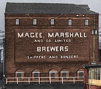
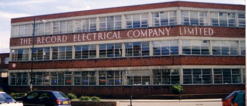
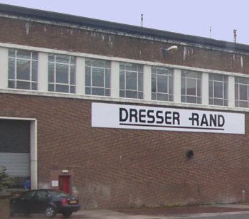
In the pre-war period factories often had the name of the firm and what they produced painted in large letters on the side of the building, often this was achieved by painting individual bricks or built-in using different coloured brick.
Fig ___ Simple sign on a warehouse end wall
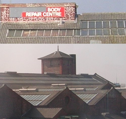
These markings can be painted on using a stencil to draw the outlines of the letters onto the embossed brick plastic card or printed brick paper, then filling in the enclosed bricks with a pale shade of paint. Watered down gouache allows the printed brick pattern on brick paper to show through. Lettraset type rub-down lettering never seems to quite look right and when I tried it I spent more time trying to blend it in than if I had elected to paint the letters as above. Some of the lettering used was quite stylised and this can be difficult to replicate, in the case of the example below (a firm providing meter and other equipment repairs to other firms) the lettering could best be replicated by using a computer to print out paper brick 'overlays' and laying these down on a shell of clear perspex, with the window frames added using microstrip (printed windows are not very effective when the windows themselves would be clean as here)
Fig ___ Photo of a building with elaborate lettering in the brickwork
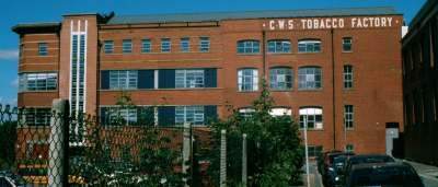
One point to note is that the brickwork lettering was placed where it would be visible. The example shown below is the former CWS tobacco factory in Manchester, the lettering is toward the end of the building as when it was built there was another large factory on the site of the car park on the right of the picture. The lettering was positioned so it would be visible from the street on which the photo was taken.
Fig ___ Photo of a building with off-set lettering in the brickwork
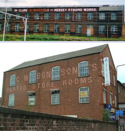
Where the building has been converted, one partner has left the business or the firm has changed hands all or part of these markings were sometimes quite crudely painted over with a red paint, in general this was not very effective as the white glazed bricks used for the letters did not take paint very well.
Fig ___ Photos of buildings with painted out brickwork name
Industrial Building Materials and Basic Structural elements
With the general standardisation of building materials and techniques there evolved a number of common building types which can serve for a range of industrial uses. Many of the 'typical' industrial buildings are easy to model and may be used in a range of model industrial settings. It should be noted that 'factories' often (one might almost say 'usually') changed use over the years, a characteristic of many older industrial buildings is the number of modifications done to the structures. Bricked up doors and windows, odd looking pipework and electrical cables running on the outside walls and extensions in slightly different coloured brick are all common.
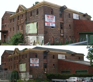
The example below is an original warehouse on the Bridgewater canal, south of Manchester. The original rather handsome building with stone capping to the walls, has been modified in various ways over the years, in the 1930s a large extension was built with a corrugated iron roof and a flat roof over the loading bay, this extension is visible to the left, on the far side of the building in the photographs. More recently a further extension has been added (visible on the right) on the dear side of the building in uniform coloured modern brick.
Fig ___ Warehouse on the Bridgewater canal (pre-dates the railways)
Building construction methods had stabilised following the Renaissance in the sixteenth and seventeenth centuries. All the technologies of classical Greece and Rome had been rediscovered and many were improved upon.
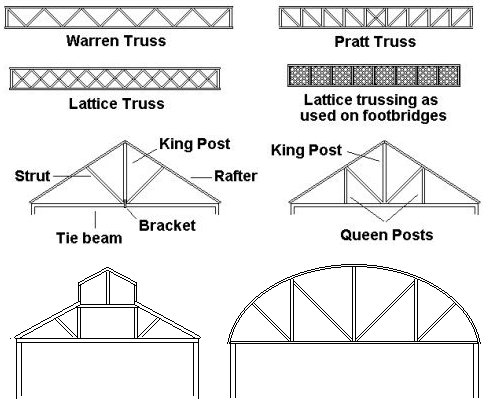
One of the more significant elements re-discovered at this time was the timber trussed arch support, used for both pitched and also for curved roof forms. This has relevance to the model maker as in industrial buildings the end of the building might be open, revealing the roof supports. By the end of the nineteenth century spans of over a hundred feet were regularly supported by trussed timbers and the principles were applied in building large timber structures such as cooling towers (Fig ___) and sulphuric acid 'lead chamber' buildings (Fig ___).
The triangulated truss structure was developed in the later nineteenth century for use with iron. These evolved though a series of designs, each with its own strengths and weakness' and the full lattice truss offers as much support as a solid 'I' beam but with a much lower weight. Trussed metal framing was used extensively for railway signal gantries, bridges and also for supporting structures such as those at the base of concrete cooling towers.
Fig ___ Trusses for supporting pitched and curved roofs.
There were two main areas in which the Industrial Revolution influenced building design. Most obvious were the large factories built to make the best use of a single source of power, however there were also a great many small work shops, often built onto peoples homes. In these small workshops the nuts, bolts, nails and chains were made for industry and crafted goods such as lace and embroidered cloth were produced. These smaller workshops and other industries, such as agriculture, which did not have their own railway connection are considered separately at the end of this section.
The basic shell of a building will be built in one of two ways, for a solid 'works' building it will be stone, brick or concrete, (technically this is called 'mass construction'), but for lighter buildings used in agriculture, commerce and industry, a simple wooden or metal frame with some form of lightweight cladding was used (technically this is 'frame construction' but the term 'shed' is often used for these buildings).
Fig ___ Example of frame construction
(corrugated iron walls, corrugated asbestos cement roofing)
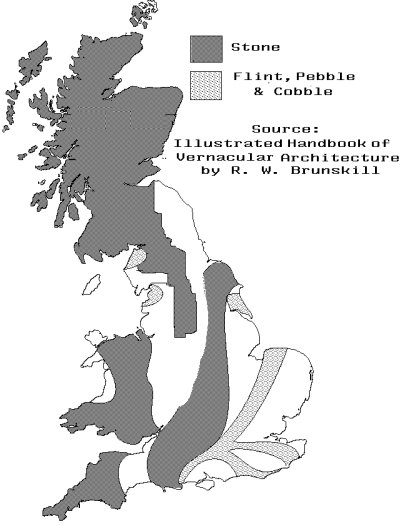
Old factories and smaller workshops were originally built of local materials and incorporated local design features, this is called 'vernacular architecture'. This died out quite quickly after about 1900 as standard materials and the methods to transport them developed. The best book I have found on this aspect of building design is R. W. Brunskill'e 'Illustrated Handbook of Vernacular Architecture (Faber & Faber 1970) which is available through the library. Mr. Brunskill confines himself to the architecture of low-budget domestic structures (houses), farm buildings and small workshops but there is a lot of useful detail in his book.
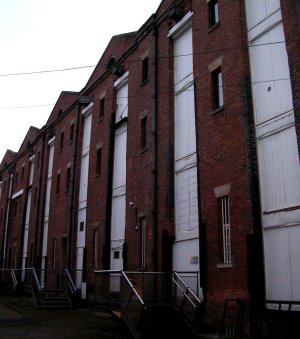
As the industrial revolution wrought its dramatic changes on British society (from the later eighteenth century and continuing through the nineteenth) there was a marked shift toward larger scale industry. This required new methods of building to be developed and this in turn influenced the building materials used for industrial structures. By the 1840s most of the familiar modern building materials were available and there was a general trend toward nation-wide standardisation of design. Older existing buildings of substantial construction, flour mills and the like, built using older methods remained in use but the new factories were almost all built of brick (stone was used in some areas, notably in the North of the country) with either Welsh slate or corrugated iron roofing. The example shown below is the goods warehouse built for the Liverpool and Manchester Railway at the Manchester terminus. The railway was elevated and on the track side of the building the warehouse was only two floors high whilst the yard side (as shown) was four floors high. This building is now part of the Manchester Museum of Science and Industry.
Fig ___ L&M Rly Warehouse built in 1830 at the Manchester terminus
Timber Framed Walls
There are three ways of building a wall from basic timber (i.e. not including plywood), you can assemble logs one on top of the other and jointed at each corner, alternatively you can erect heavy posts and drop heavy timber planks between them or you can build a simple frame of timber and fill in the gaps with something else.
Only the last of these methods has been regularly used in Britain, so beware as some continental model buildings are based on the log or plank type of construction.
There are two types of timber frame construction used, called 'cruck' and 'box frame'. A cruck type structure has tall, inclined and often curved timbers reaching down from the apex of the roof to the ground to carry the load of the roof. A box frame as the name suggests supports the roof timbers on the wall frame. This distinction is not absolute, some 'cruck' type building had jointed sections, but broadly speaking the distinction holds true. Cruck construction was only used for agricultural buildings by the later eighteenth century.
Timber framed buildings date back to the middle ages, from the broad definitions mentioned above they can be either 'buildings' when the frame was filled-in with some solid material such as brick, or 'sheds' when it was clad in wood or corrugated iron.
The material used to fill in the gaps in a timber frame building might be brick, cobbles, pebbles or flint. Cobbles are rounded stones recovered from rivers and glacial moraines, pebbles are similar stones recovered from the sea shore and Flint comes in blobs which tend to be rather egg shaped, it is found only in the chalk beds to the south east of the country.
In older buildings they usually used a basket work of wood covered with a 'daub' made of clay, horsehair, dung and other materials. In cases where the in-fill provided poor protection from the weather it was usual to add a coating of sand-lime plaster inside and out. In the North Midlands, Cheshire and Lancashire it was usual to paint the timber with black pitch and whitewash the plaster but elsewhere the natural weathered oak framing was complimented by colour-washed panels.
In central Manchester there are some of these half timbered buildings, the original 'shambles', currently in use as a resteraunt. Not all such buildings are old however, the photo below was taken in Northwich Cheshire where the Victorian answer to mining subsidence was to use this form of construction so that the individual timbers of the buildings could be jacked up
Fig ___ Timber framed buildings
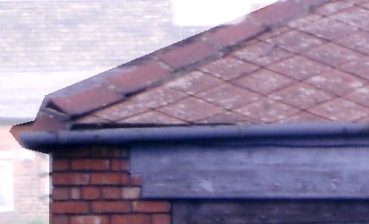
When clay roof tiles became cheap another option was to add strips of wood to the outside of the building and hang the tiles from these to form a waterproof cladding. The standard roofing tile (typically about ten inches by six inches) was often used but decorative effects were obtained using shaped tiles.
One curios variation was 'mathematical tiling' which uses tiles cast to resemble brickwork, this first appeared in the mid eighteenth century and remained popular into the middle of the nineteenth. Tile cladding became quite popular in the South East of England in the early nineteenth century.
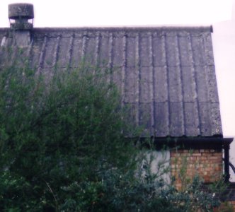
For industrial structures the two most common cladding materials were corrugated metal (discussed below) and wooden planks (called weather boarding). Asbestos mixed with cement and pressed into thin sheets was used for industrial buildings but this was not very strong so this material was mainly confined to roofs. This was used in flat sheets for the walls of domestic garages and in foot squares as a 'shingle roof' material (usually laid in a diamond pattern)
Fig ___ Asbestos squares laid 'diamond pattern' on a small industrial building roof
Another option with asbestos cement roofing is corrugated sheets similar to corrugated iron and also in narrow strips with two large corrugations, one at either side. This latter, supplied in long curved sections, was used for flat and curved roofs on industrial buildings and a visually rather different from the more common corrugated sheets. The example below was photographed in 2005, it is worth noting that this form makes modelling using wound thread rather easier as comparatively few windings are required, although you do need to mark up the card first to ensure regular spacing (any error would be very visible even in N)
Fig ___ Formed concrete/asbestos sheeting used on an industrial building
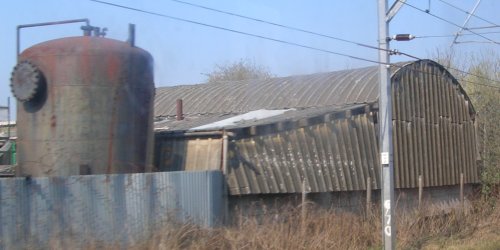
There were occasions where this asbestos material was used for industrial walls, in locations where they would be unlikely to get hit by anything hard. The example below is on the outskirts of Altrincham, the roof and upper walls are all made from corrugated asbestos-cement sheeting. The photo was taken in 2007 but the building, and the curious tank beside it, have been there since at least the early 1970s (quite possibly a lot longer).
Fig ___ Corrugated asbestos cement cladding
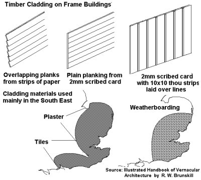
Weather-boarding might be used to cover a wattle and daub wall but in the case of farm or industrial buildings it would simply be applied over an open frame. Weather-boarding became popular in the later eighteenth century mainly in the South East (where it was seen on houses) but it was used all over the country for cladding shed type structures used for agricultural, industrial and commercial buildings. Relatively few homes were built with weather-boarding cladding in the rest of the country although where I grew up in North Cheshire there were occasional examples of single storey detached timber houses, a few of which lasted into the 1980s.
The most common arrangement used the boards nailed horizontally, each one overlapping the one below. A less common alternative was but-jointed wooden planks forming a flat surface, for this I would suggest 2mm scribed planking would probably look better (this scales out at fractionally over a foot, ten inch planking would be better but I know of no supplier of 1.6 mm scribed card). A third method was to mount the boards vertically and add narrow strips of wood over the joints, this technique was often used on church towers and spires and there was at least one railway wagon workshop in the South East with this kind of walling still in use in the mid 1980s. Again 2mm scribed card serves as the base, with strips of 10x10 thou glued along the scribed lines (the scribed lines help keep them at regular spacing).
Fig ___ Timber cladding on timber frame structures.
There were some local alternatives used in cladding timber framed walls, corrugated metal was widely used, with corrugated asbestos sheets for the roof, roofing slates have been used in the South West of the country and in North Wales and the Lake District. I have seen examples of slate cladding to give additional weather protection on the exposed gables of brick-built buildings in Manchester.
One curious example is a building clad in cast iron plates to be found in Kendal (Westmoreland). The use of cast metal to imitate stonework on timber buildings was common in America and Australia but quite rare in Britain.
The Americans with their plentiful supply of softwoods developed a new method of timber building in the Nineteenth century. This was the 'balloon frame, made up of vertical 'studs' of two inch by four inch timber with a wooden cladding applied to the outside. If the cladding was planks then diagonal braces were built-in to the walls, if the cladding was sheet timber no additional bracing was required. Floor supporting joists and roof timbers were usually ten inch by two inch timber. The outer walls were often weather-proofed with a coating of stucco, usually white-washed. Windows and doors were simply cut through the frame as required and the whole assembly was easy to build using only cheap machine-made nails. By the end of the nineteenth century this form of construction was seen in minor British industrial buildings. Single storey buildings required only the lightest of timber frames, typically the verticals might be spaced at three or four foot intervals.
Stone
In areas of the country where suitable stone was available it was regularly used for industrial buildings up to the late nineteenth century, after which the basic brick structure became a national standard. The Victorians were in the habit of using square-cut stone (called Ashlar) for the public frontage of a building, with cheap standard bricks for the sides and the cheapest brick at the rear. This was mainly confined to commercial rather than industrial buildings however there were examples of this form of construction in the industrial landscape. One example might be an electricity generating station, where the appearance of solidity and reliability were, to the Victorians at least, enhanced by an imposing stone facade. The use of cheap brick to the rear of the building often resulted in a rather dilapidated appearance on this side even when the building was new.
Fig ___ Areas where stone was regularly used for building.
Brick
Bricks had been in limited use in the Eastern Counties in the Middle Ages but became much more widespread in the sixteenth and seventeenth centuries. Brick became a fashionable building material in the seventeenth century but they were hand-made and so expensive. The introduction of machine made bricks, where the clay is forced through a square aperture like toothpaste and cut to length with a wire frame, reduced the cost of bricks although hand made bricks continued in production into the 1960s. Even so brick did not replace traditional building methods until the later half of the nineteenth century.
Brick construction generally replaced timber framed building, so in areas where stone was widely used brick buildings were often confined to larger industrial premises. Occasionally when sinking mines clay of a suitable nature for brick making was encountered. This usually lead to the building of a brick works, even in areas where the tradition of building in stone was strong, in these areas stone was often used for door and window frames in new brick buildings.
The change to brick construction was not without its problems, especially in areas where timber framed buildings had once been the norm. Builders were unused to the technical problems of 'mass construction' and one often sees buildings in these areas with metal plates on the outer walls, linked by iron rods running through the building, installed when the walls began to sag outwards.
As bricks became popular in the late eighteenth century 'brick taxes' were introduced (on both bricks and clay tiles). These remained in effect, with varying levels of charge per brick, into the mid nineteenth century and were only finally abandoned in about 1850. As the tax was based on the number of individual bricks used one side effect was to vary the size of bricks. The standard 'footprint' of bricks (about nine inches long by four inches wide) remained but when the taxes were low they were much thinner (perhaps two inches) as this required less fuel when firing the bricks. When the tax was high the thickness increased, reaching a maximum of about four and a half inches.
Early brickwork had no recognisable pattern in the way the irregular bricks were laid, this meant the walls were not terribly stable and various 'bonds' or patters of laying bricks were developed. As it is assumed the reader will be using commercial brick paper or brick embossed card the details need not concern us here (the bond is near invisible in N in any case).
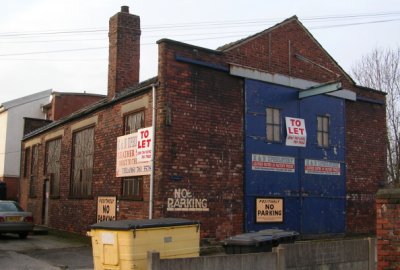
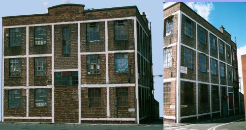
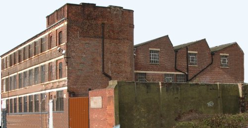
By the 1840s the standard British brick was in use but as these were made in hand-stacked kilns (discussed below) the colours of the bricks varied depending on where they had been in the stack when fired. Uniform colour bricks really only became common in the 1860s. The photo below shows a typical industrial structure of indeterminate age. The building was evidently designed to handle something rather large as the end walls are built up to carry the rails for the large sliding doors, I believe it was originally a forge, working with wrought iron and steel (for example making leaf-springs for road vehicles).
Fig ___ Typical brick-built 'back street' industrial building
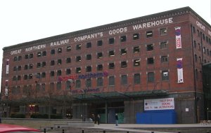
The deliberate use of different coloured bricks for decoration was popular, although mainly confined to the front or 'public' face of the building. The Great Northern Railway Company Goods Warehouse in Manchester still bears that legend as the lettering was made up of white glazed brick. Terra-cotta bricks and bricks with moulded shapes came into play in the eighteenth century, providing enhanced decorative possibilities. More information on brick colours will be found in the section detailing brick, tile and clay pipe works.
Fig ___ GNR goods depot building in central Manchester
In the early nineteenth century bricks fell from favour for a time and an external coating of stucco in a general imitation of stone became popular. Again this was mainly confined to domestic and commercial buildings rather than agricultural and industrial structures.
Iron and Steel
Iron has been used as a building material for some time, the Chinese built suspension bridges using iron chains as long ago as the fourteenth century. St. Anne's Church in Liverpool used solid iron supporting columns in 1772 but the worlds first major all-iron structure was the iron bridge, built over the gorge of the River Severn in Shropshire, in 1779. This bridge is made up of five separate iron ribs and the design uses interlocking parts with no nuts, screws or rivets at all. Subsequent iron structures favoured either nuts and bolts or for heavier structures rivets.
Welded joints were generally weaker than riveted joint prior to the 1950s, on ships with a welded hull the join between the deck and the side of the ship had to be riveted by law into the early 1970s. Welding is achieved by melting two bits of material so the joint line merges. Welding actually dates back to about 4000 BC but this was achieved by forcing the red hot metal edges together after heating in a furnace. This remained the only practical way of welding metal until the mid nineteenth century when an American engineer called Elisha Thomas developed electrical resistance welding. The two pieces of metal are laid together and an electrode is placed on each side of the joint. When electricity is passed through the metal it heats up due to its electrical resistance and as most of the heating occurs at the joint where the resistance is greatest, this melts the metal along the join which fuses together as it cools. Resistance welding was used to make welded steel pipes as early as the late 1880s.
The electric arc was originally developed in 1807 by Sir Humphrey Davy (1778-1829) but it was 1885 before someone devised an electric arc welding kit. In arc welding one electrode is attached to the piece to be welded whilst the other is held in the hand, the arc is struck by touching the hand held electrode to the piece and drawing back slowly. In 1890 a Russian developed the consumable electrode which melts and fills the joint to produce a solid joint. In 1904 the coated electrode (as used today) was invented but it was the 1920s before arc welding became common.
Oxy-acetylene welding was invented in 1900 by Frenchman Edmund Fouche, this used cylinders of oxygen and acetylene and it was the development of the cylinders which made it practicable (see also Chemicals). Another application for oxy-acetylene is cutting and this appeared soon after the welding kits.
Oxy-hydrogen torches pre-date oxy-acetylene but they were not
used for welding (they were mainly used to burn a lump of chalk or limestone in 'lime lights' used in theatres). It was the cost of producing the gas and problems of containing the gasses in a safe manner that rendered this impractical. It is usual with gas welding to use a length of special rod which melts into the joint.
Some materials are difficult to weld, a good example being aluminium. If air gets to the hot metal it forms an oxide which just does not weld together. The solution, developed in Manchester, was to add a third pipe which blows some inert gas over the joint during the welding process. The gas used has to be selected with care to ensure it does not itself react with the metal.
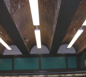
By 1800 textile mills were built up to seven stories high using hollow iron columns for internal support with masonry exterior walls to give the structure lateral stability. To make the building fire-proof the internal floors were supported by brick arches resting on inverted T section iron girders resting on the columns. Later reinforced concrete (described below) was used for the floors but tubular iron supports were not replaced by reinforced concrete pillars until well into the twentieth century. The example below is the underside of the elevated concourse at Piccadilly Station in Manchester.
Fig___ Brick arch 'fireproof' construction
By 1820 iron was being used for roofing, notably on the wall-less iron 'sheds' built in Liverpool Docks in about 1818. Combined with traditional brick load-bearing walls iron made possible the great arched roofs of the railway termini such as Brunel's roof on Paddington station built in 1854. Cast iron was used where the load was under compression such as in pillars and wrought iron was used for loads under tension such as the internal stressing for the great arched roofs of the railway stations.
All-iron buildings developed more slowly, an early example was Hungerford Fish Market in London (1835) for which timber was banned on the grounds of hygiene. Iron building components had one serious flaw, in a fire the iron became weak if the temperature rose above about five hundred degrees centigrade. To help the building withstand fires iron girders are usually encased in a couple of inches of concrete.
Iron did have several advantages, not least of which was that they were easy to standardise and in the nineteenth century Britain exported a lot of prefabricated iron buildings, houses, churches, warehouses and even lighthouses. Particularly popular in America and Australia were the cast iron 'store fronts'. The Scottish iron industry was a major producer of these building 'kits' with Glasgow as the main exporting port and Australia as their main market.
There is a surviving example of an iron building on Jamaica Street in Glasgow, originally built as a furniture warehouse it is now a shop. A lot of the ornate 'stone' columns decorating the front of Victorian buildings were in fact made of iron cast into the required form with textured stone paint was then applied over the top.
Cast iron was a popular element in 'engineering' buildings such as the preserved warehouses on St. Catherine's Dock in London (built by Telford in 1824) and the big new textile mills built in the Pennines and the Cotswolds.
Corrugated iron was invented in 1825 by a London builder called Richard Walker, the corrugations make a thin sheet of metal much more rigid. One of the earliest uses was for roofing buildings at the Royal Arsenal at Woolwich, the idea being that the relatively light sheets would cause less damage if the building blew up.
Walker hand-shaped the iron sheets but in 1844 a Birmingham firm patented shaped rollers which reduced the cost and the material soon gained wide acceptance for domestic roofing as well as industrials roofs and wall cladding. The addition of the galvanised zinc coating developed in 1880s made it rust proof and it soon became a common building material in both industrial and also, to a lesser extent, domestic structures.
When I was a military modeller I produced a lot of 'corrugated iron' using bolts or threaded bar to emboss aluminium cooking foil. Ideally you need something like a mouse mat (or any fairly firm sheet of rubbery material, I used to use a scrap of rubber insertion jointing from the ships engine room), you lay the foil on this and tape the ends down and roll the threaded bar or bolt along whilst pressing down (a foot of 1"x1" timber is handy to press down with as you roll). For odd sheets you can produce lengths by holding a strip of foil firmly against the bolt with your thumb and pulling it through as shown below.
Fig___ Making corrugated iron sheet
Having built the main structure in card you can then clad it in the sheets using Evostick or Bostick adhesive, do not press down however as this will flatten the corrugations! Aluminium foil can be glued to paper with PVA wood glue but personally I prefer latex glue and this is the best option when sticking foil to plastic. When painting use well thinned paint, the end result is quite resistant to handling, at least for buildings, and I have formed the sheets round various curved formers and the corrugations remained clearly embossed. An alternative for flat sheets is to use sections of Ratio corrugated walling to crimp squares of chippy foil, I have not tried this myself however and I suspect the result would be well over scale.
Most corrugated iron was used in the form of plain flat sheets but by the turn of the century it was being used in curved sheets as seen on the Ratio corrugated iron roof (supplied with their carriage shed kit and also available separately). In the 1880s the new Royal Albert Docks opened in London, boasting single storey transit shed made up of two spans each sixty feet wide. The buildings were described as being 'almost entirely made of iron'.
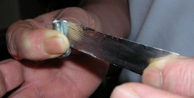
One option for occasional use is to wind thread over a card former, done with care this can produce excellent results.For modelling OO scale Nissen huts see Appendix X - Wargame Scenery - Simple Buildings. For N using mono-filament fishing line would be preferable to cotton thread, however for one odd scrap of roofing I used cotton thread and the result is (to my eyes) acceptable.
The photos below show a large building with corrugated metal walls and roof currently used as a stores and workshop for tall 'straddle carriers' at the Containerbase container depot in Trafford Park and another large 'shed' type structure clad in corrugated metal but with a corrugated asbestos roof (Northwich, Cheshire).
Fig ___ Corrugated Iron Buildings
Glass mounted on an iron or steel frame, technically known as ferro-vitreous but more often called 'glass cage' construction became practical in the early nineteenth century. Early examples were greenhouses, the Palm House at Kew Gardens was built in the 1840s and is still standing. Ferrovitrous construction reached something of a peak with the Crystal Palace built in 1851, the technology allowed the designer (Paxton) to use iron columns to support a light lattice structure made entirely of pre-fabricated parts and clad in glass.
Steel became an important building material after about 1855, one significant use being in the heavy I section joists over doorways. By the late 1870s steel rolling had improved to the point where deep H section girders could be made which in turn allowed very tall steel-framed buildings to be built.
Tall buildings or 'sky-scrapers' had little impact on the industrial building practice as very tall buildings had more problems than advantages. Tall buildings caught on in crowded American cities, first in Chicago, later in New York. These were mainly dwellings and offices and one important element in their development was the steam powered elevator or 'lift' developed in 1854 by Elisha Otis (1811-1861). People had proved reluctant to climb more than five flights of stairs and the new American structures were called 'elevator buildings'. It is perhaps worth noting that the Roman had built blocks of workers 'flats' in concrete that were up to nine stories tall.
In some heavier industrial applications the steel frame was visible on the outside and a good example of this is the large gas works building shown in Fig ___.
The joins in iron and steel framed buildings were riveted up to the 1970s (some still are) and it was common to add an extra plate across the join called a 'doubling plate'. This makes the modellers job easier as we can cut the plate from paper or Bacofoil and use a pin to emboss the rivets onto it before gluing it in place.
Fig ___ Riveted doubler plates
Steel framed industrial buildings were not all of the 'shed' type, some had the spaces between the girders filled-in with brick. The example below is part of an extensive factory building, adding the visible framework would provide more visual interest were it used as part of a backscene.
Fig ___ Steel framed industrial building
Where fire was a danger the steel was clad in concrete, heated above a few hundred degrees steel looses much of its strength but two inches of concrete is usually considered enough to protect the iron or steel frame. This combination of plain or concrete-clad steel frame with brick in-fill can be easily modelled by covering the building in brick paper then laying down strips of paper to represent the frame, use green or 'track colour' for plain metal, white for concrete coated. Lay the strips horizontally at each floor level and vertically at ten to twenty foot (3m to 7m) intervals, to form a grid. Note the windows would usually extend up to the beam above with no brickwork on top. If you opt for the concrete coated steel you do not need to add rivet detail to the joints in the frame. The building shown below has its original entrance bricked up, access now being via the enclosed yard at the rear, but it remains a factory producing clothing.
Fig ___ Steel framed industrial building with sheathed steelwork
Some of these buildings have brick cladding over the frame, one example is the original Ford motor car factory on the A34 in Stockport, south of Manchester, dating from 1928. The building has a steel frame clad in concrete with a brick overlay and brick in-filled walls, the roof is flat. The show room was on the ground floor and a heavy lift was provided to transport the cars to the workshops on the upper levels. The tall windowless extension on the roof housed the heavy lift machinery.
The photo below was taken in the 1980s, the building has since been redeveloped with a new glassed in roof and the ground floor is now all plate glass panels.
Fig ___ Original Ford motor car factory in Britain.
Mortar, Cement & Concrete
Mortar for brick work was made from lime and sand mixed with water, this dries in the air to form a solid material. It will not set under water however and so could not be used to build the walls of canal locks or the foundations of lighthouses built on rock outcrops in the sea.
Cement sets by a complex chemical reaction and will therefore set under water. The Romans knew about cement and used it to build roads and buildings but the secret was lost when they left. It was only in the eighteenth century that people began to experiment to find a mortar that would set under water that the secrets were re-discovered.
Cement manufacture really began with the development of Portland Cement by Joseph Aspdin of Leeds in the 1820s and within thirty years major cement works were established at Swanscombe and Northfleet in the South, Wakefield in Yorkshire and on the East Coast at Gateshead and Hull. There were also many smaller firms who built their factories anywhere that limestone or chalk was available. Modern cement was developed in the 1840s and in 1854 William Wilkinson patented reinforced concrete in Britain.
In the 1850s French builders started erecting concrete buildings reinforced with wrought iron I beams but in the 1860s a French gardener patented a method of making very large flower pots using cement reinforced with a mesh of iron wire. The French architect Hennebique (1842-1921) took this idea and used it to make floors and walls in multi-storey buildings.
Concrete structural elements appeared in the 1870s, the reinforced concrete beam was patented by the Frenchman Joseph Monier (1823-1906) in 1877, by which time that the iron and steel industry was able to produce the rolled girders to make these concrete structures viable.
Buildings built with concrete were not initially popular in Britain but were widely used and mainly developed in the USA and in France. Even so it was the turn of the century before concrete columns were used in any numbers and even then brick was commonly used to fill in the walls. Large buildings using concrete columns and beams reinforced with steel appeared in Britain in the first decade of the twentieth century.
The dock walls of the Royal Albert Docks in London were built using a mass of poured concrete in the 1880s, this was closely followed by the first significant all-concrete building in Britain, the Weaver & Co Ltd flour mill at Swansea in 1898. The flour mill was actually built by two French pioneers of concrete construction, Hennebique and Le Baun (1821-1901). This was followed by a concrete viaduct on the West Highland Extension Railway, built using the French methods by McAlpines and finally opened in 1901. The first factory built in concrete was the Rose Downs and Thompson's Factory at Hull built in 1900.
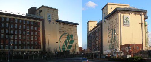
The British remained reserved however and it was only in the 1920s that concrete structures began to appear in numbers. Most builders favoured the French Henebique system of building and this was used to build mills and factories all over the country. The example shown below is a flour mill, the concrete structures at each end of the building are the silos in which the grain is stored. On a railway layout similar structures, normally associated with docks, might supply grain to railway hopper wagons for inland distribution.
Fig ___ Typical concrete grain silo at a flour mill
In 1926 Eugene Freysinnet began experiments on pre-stressed concrete in France and in the 1930s the American government substituted concrete for limestone during federal building projects of the Great Depression. At this time concrete began to be used extensively for pavements , road-beds, bridge approaches, dams, and sports facilities (stadiums, swimming pools, tennis courts, playgrounds). Following the Second World War there was much use of poured concrete to rebuild war-torn cities of Europe.
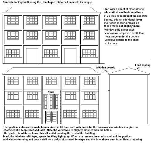
Concrete buildings often had metal framed windows often resulting in a characteristic 'flush glazed' look. Buildings with concrete or brick walls and metal framed flush windows are best represented by building the structure of clear plastic card and adding detail from thin plastic card and paper. The window frames can be represented using strips of painted Sellotape but I would advise drawing a plan on paper and placing the wall on this to accurately lay up the frames so they are all identical.
Fig ___ Henebique method concrete factory building
By the 1880s the flat concrete roof was becoming a practical proposition (these are discussed below under roofing materials) and by the later 1930s it was possible to build large shallow domes or arches over working areas entirely out of concrete. The first substantial British building to use this dome technique was probably the rubber factory at Brynmawr in Gwent built in 1951.
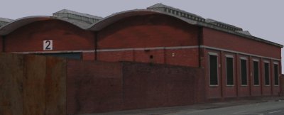
Curved roof structures have been around for a long time (the Romans built several domes in concrete) but they were not widely used in industrial applications until about the mid 19th century when corrugated metal cladding became available. Initially curved roofs were associated with light weight 'shed' type structures, often with only partial sides. A timber or metal lattice frame was used and the roof itself was made up of flat corrugated sheets or curved sheets bent to suit the line of the frames. The great railway termini favoured the curved roof structure as it allowed a considerable span between supports. This type of structure gained further importance in the 1920s when it was used to build airship and aircraft hangers. By the 1930s the curved reinforced concrete roof was a viable proposition but most examples seem to be post war structures, the example below has a roof made of a sheet of concrete in the form of a low arch on a brick walled base, giving a clear space beneath the roof with no trussing.
Fig ___ Curved concrete factory roof with roof lights
Roofing Methods
Building a weather proof roof has presented a problem to everyone who has erected a building. The design of the roof was the main restriction on the actual ground plan of a building up to the introduction of the flat roof.
The most common roofing material on industrial buildings from the middle of the nineteenth century to the 1960s was slate, with the development of the railways most slate was shipped from North and West Wales. Welsh slate is supplied cut to standard thickness' and shapes. Slate from other areas (Cornwall, Devon, Leicestershire, and the Lake District) were supplied in uneven thickness' and odd sizes, these remained in use locally and were normally laid using progressively smaller slates as you proceeded up the roof.
Slate roofs are usually pitched at an angle of about thirty to thirty five degrees but (especially on smaller out houses) they can be laid to a flatter pitch.
The second most important roofing material for industrial buildings is the corrugated metal sheet, augmented in the 1950s and 60s by corrugated asbestos sheeting. Both these materials can be represented by the embossed bacofoil described above, corrugated iron roofs were usually either dark red or green, asbestos sheeting was a light grey colour but being concrete based tends to accumulate moss. Curved corrugated iron roofing is available as a unit from Ratio however this is rather 'heavy' for N and an alternative method for making such a roof is described below under Nissen Huts.
.
Fig ___ Asbestos roofing on small industrial structure
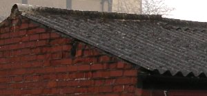
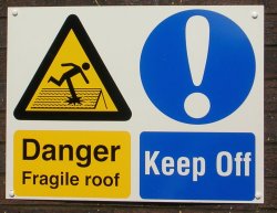
Asbestos roofing is not very strong, walking about on a roof covered in this material was a dangerous business and on more modern buildings, where light (cheap) construction is important flat roofs are often flimsy by Victorian standards, By the later 1980s it was standard practice to add warning notices regarding the strength of roofs and by the end of the 1990s they were a regular sight. The example shown below is a large type, many have only the left hand panel and do not have the additional instruction to keep off.
Fig ___ Fragile roof warning sign
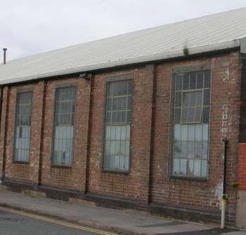
By the 1970s new methods of rolling sheet metal, and treating the surface, saw the introduction of formed metal panels for the roofing on industriual buildings. This was widely used on the pale stock-brick building errected on the new industrial estates but was also occasionally used to replace old roofing on existing buildings as shown below. Note also the flat metal industrial window framing with tilting 'opening light' (open in the nearest window).
Fig ___ Pressed metal post-war roofing
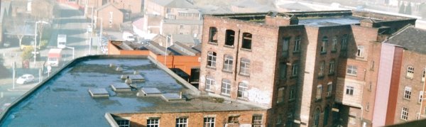
Where buildings were large the usual option was to add a series of pitched roofs in a saw-tooth pattern along the top, usually timber with slate covering, occasionally lead sheeting was used. The development of reinforced concrete in the later nineteenth century allowed the building of flat roofed structures and many of the later brick-built mills and factories in the North have flat roofs. A flat concrete roof costs less to build than a conventional roof and when the tenements in Glasgow were built, the first 'high-rise' flats, flat roofs were used, unfortunately the roofs were not all of the best quality and leaks were not uncommon.
Flat roofs are not actually flat, they generally have a slope of between 1:100 and 1:60 to allow water to drain away to the side. Flat roofs are usually surrounded by a low parapet typically eighteen inched (45 cm) to two feet (30 cm) high topped with flags of concrete or occasionally with shaped ridge tiles. The concrete is porous so a covering was added, usually two or three layers of tarred felt. This was taken up the inner sides of the parapet to a height of a foot or so and bonded to the brickwork.
Fig ___ Typical industrial flat roof.
More recently flat roofs have been produced by laying down sheets of chip-board and coating this with tarred felt, these roofs have proved less reliable in practice and as building sizes have increased heavy falls of snow have occasionally caused them to collapse. Tarred felt will eventually start to leak but repairs are easy to effect by simply heating up some tar and pouring it over the affected area. In the 1950s it was found that a lighter coating of tar could be used if the felt was covered in a layer of small (usually white) stones.
Wooden planking or 'weather boarding' has been used for roofing, mainly in the south east and usually associated with older industrial buildings, notably those on old water-mills.
Elsewhere timber was sometimes used where the roof incorporated unusual shapes, for example most roof ventilators were built of timber. The only way to represent a weather-boarded roof is to lay strips of paper, which takes patience, the end result however can be very pleasing. Timber tiles, called 'shingles' have been used to a limited extent in Britain, often laid to produce a diamond pattern on the roof. This was often subsequently covered with tarred felt strips.
Tar-proofed felting weighs little and can easily be nailed down over a light framework, this made it a popular choice for smaller timber framed buildings such as petrol filling stations and garages. The early types of felt roofing material were blackish grey in colour but by the 1950s they were usually given an external coating and the standard colour was medium green.
It was supplied both in rolls about four feet wide and also in squares (called 'shingles') which were typically about two foot (60 cm) square. The rolls were laid either down the roof in strips or along the roof, in either case the join was achieved by over-lapping the material by about three inches and sometimes a little bitumen was used to glue the edges down. Similar square tiles or shingles made of asbestos fibre bonded with tar became popular for lighter structures such as garages and filling stations in the later 1930s.
As with the timber shingles the felt or asbestos squares were often laid to form an over-lapping diamond pattern on the roof, and the colour was usually a light grey which soon became stained and supported moss on the shadowed side.
Fig ___ Asbestos squares laid 'diamond pattern' on a small industrial building roof
Lead sheet, supplied in two to three foot wide rolls, was sometimes used for roofing, the edges of the rolls were formed into interlocking U shapes and pressed flat to make the join waterproof. Lead roofing was more expensive than the other alternatives and so was not very common on industrial buildings, usually it is associated with larger country houses and churches.
One area where sheet lead proved popular was on complicated roof shapes such as coned turret roofs on towers. The lead was not usually cut into any complicated shapes but was simply laid over the shape in sheets and bonded down with bitumen at the joints.
Fig ___ Lead on a cone shaped tower roof
The above photograph is of a tower on the facade of Deansgate railway station in Manchester.
Plain tile roofs became popular as brick making developed about five hundred years ago. The standard size for a roof tile (ten and a half inches by six and a half inches by half an inch thick) was established in the later fifteenth century. Tile roofing, like brick walling, was originally confined to the South East but being fire-proof they proved popular in areas where slate or stone was not readily available. Anywhere a local brick works set up was likely to see at least a proportion of the buildings with tiled roofs, although these tended to be domestic or commercial buildings rather than industrial.
Tiles are usually used with quite steep roofs, typically forty five to fifty degrees, and specially moulded ridge and valley tiles allow complex roof shapes to be built up.
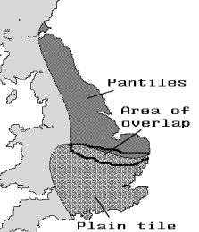
A variation is the pantile, which has a shallow S shaped curve so that the tiles interlock. Used by the Romans they were re-introduced from Holland in the eighteenth century and the standard size (thirteen and a half inches by nine and a half inches by half an inch thick) was established in the reign of George I. They were widely used, mainly for domestic buildings, all the way up the east coast from London to the Scottish borders but other than for a small area in Somerset they were not used in the western areas of the country.
The map shows the distribution of tiles and pantiles as traditional roofing materials in the early years of the Industrial Revolution.
Fig ___ Distribution of Tiles and Pantiles
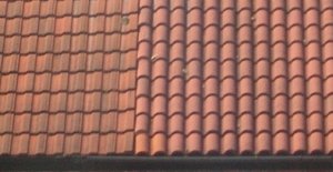
In the 1960s a new roofing material was introduced, thick tiles usually called 'Marley tile', in the photo below the tiles on the left are the modern type, those on the right are the traditional type.
Fig ___ Pantiles
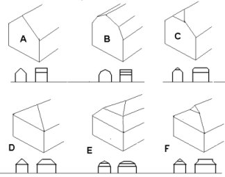
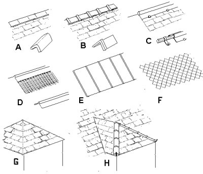
There are only so many basic roof shapes, the differences lie in the ends and broadly speaking these are divided into plain flat 'gable' ends and inclined or 'hipped' roofs.
Looking at Fig ___ sketch A shows a plain gable end, this was the most common type associated with industrial buildings.
Sketch B shows a gabled roof where the roof itself is made up of two separate angles, called a gambrel or 'mansard' roof. This provided more 'head room' close to the walls and was used where the roof space was required for storage. This was a common design for flour mills and was occasionally seen on maltings, both of which used the roof space to store grain.
Sketch C shows a 'half hipped' roof, more common in the south and east of the country than elsewhere these were occasionally used on the end of terraced rows of houses especially if the corner position was occupied by a large shop.
Sketch D shows a basic 'hipped roof', common on semi-detached and detached houses, not very common on industrial buildings.
Sketch E shows a variant on the gambrel roof called a 'hipped gambrel' or mansard roof. Not very common at all.
Sketch F shows a curious design of hipped roof with a gable incorporated near the top, this was occasionally used where a ventilation opening was required, usually this opening was protected by a louver. This arrangement was however not common on industrial buildings.
Fig ___ Roof shapes & Common Terms
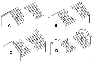
With gable ended structures you need some way to stop the rain getting in under the join of the roof and the gable wall. With a slate roof you can simply build up the top of the wall with cement to fill the gap, alternatively you can nail wooden planks called 'barge boards' to cover the gap (Fig ___ A).
Another common method, particularly with industrial buildings, was to build the wall up just above the line of the roof. Strips of lead 'flashing' sealed the join between the wall and roof. To protect the top of the bricks from rain and general weathering stone flags were laid on top of the walls, this is called a 'coping' (Fig ___ B).
In some buildings the gable was built up to a height of a foot or more above the roof line, which is called a 'parapet' (Fig ___ C) and on the public frontage this was sometimes worked up into a decorative shape called a Dutch Gable (Fig ___ D).
Fig ___ Gable end types
The joint at the top of the roof is called the ridge, and you need some way of preventing water getting in along this join.
Fig ___ A shows shaped stone ridge covers whilst Fig ___ B shows stoneware (fired clay) tiles which feature a lip at one end so they overlap at the joins. The stone type can be made from small drinking straws or the innards of an (empty) ball-point pen.
The stoneware type can be represented by a single strip of paper folded over the ridge with additional thin strips laid over this to represent the ridges.
Fig ___ C shows the lead ridge, this was quite common up to the 1940s and consists of a pole to which are attached simple metal clips. The lead strip is laid along the pole and beaten into shape around it leaving a skirt to either side. The ends of the clips are then bent round the skirt to hold the strip in place. This is easy to model, lay a strip of paper along the ridge, add a length of thread or 10x10 thou plastic rod to the top and give it a few coats of light grey of paint to blend the two together.
Fig ___ D shows a corrugated iron roof with a shaped iron strip to protect the ridge, this was the most common solution for this kind of roof. Lay a strip of paper over a length of 10x10 thou rod, dampen the paper and press it down over the rod. When the paper dries gently fold it and lay it along the ridge.
Plain lead sheeting roofs as shown in Fig ___ E usually had the standard lead strip ridge as shown in sketch C.
The felt roof type usually simply had a strip of felt laid over the join and nailed through to the rafters below as shown in Fig ___ F.
Fig ___ Ridges and valleys
It is worth exploring the use of different roof styles as the roof is the part of a model you spend most time looking at. The photo below was taken in the former garment district of Manchester and offers a selection of roof styles in a single building.
Fig ___ Multiple roof styles on a single building
Thatch and plain tiles are easy to form into hipped roofs, slate, curved 'pantiles' and corrugated asbestos panels are better suited to gable ended roofs. Corrugated metal can be used with either form but most industrial buildings favoured the simplicity of the gable-ended roof.
Where a building has en extension, or where a 'dormer' extension is built into the roof, it forms a 'valley'. The join can be arranged in thatched roofs simply by sweeping the thatch over the join (giving the so called 'eyebrow' dormer shape. With stone tiled roofs specially cut stones could be arranged to 'lace' the valley. With plain tiled roofs they used specially formed tiles to fill the join. With curved pantile roofs, stone flagged roofs and slate roofs you need to fill the join, usually with a strip of lead. As a general rule if a building has hipped ends to the roof the 'dormer' will be hipped, if it has gable ends the dormer will present a flat gable as well.
The nature of a slate roof means that it is best to avoid hipped construction and valleys as it is difficult to make waterproof joints at these points. If you want a hipped slate roof you can use standard printed slate paper and claim there is a concealed lead 'soaker' running along under the corner joint.
Where a valley is formed (such as where a building has an L shape) you need to add light grey paper strips to represent lead 'flashing'. Where a chimney stack emerges through a roof you need to add similar flashing to the join between the brickwork and the slate.
Hip and valleys are difficult to form using pantiles so they are usually associated with plain flat roofs with gable ends.
If you feel able it is worth trying to make a building with a collection of roof heights and angles, for example a local bus depot featured a single large overall roof over the main building but with a series of side extensions forming a saw tooth along one side. The side extensions were at an angle to the main building with a common outer wall so the whole formed a triangular shape. Some factories had a series of pitched roofs but with walls extending to the top all the way along to form a 'false front'.
The flat roof is the easiest to model if a building is not square in plan, so consider adding a later extension with a flat roof to a hipped roof brick building.
Adding small chimneys also helps break up the scene, these were usually close to the walls.
Windows and roof lights
Another important building development of the renaissance was glass for windows, used by the Romans and re-introduced in the sixteenth century when glass makers in Venice learned how to spin flat disks of blown glass for making glass dinner plates. This was known as 'crown glass' and larger disks could be polished and cut into squares for windows.
Window design changed slowly and by the seventeenth century the most common form of window in houses and office buildings was the double-hung, counter-weighted sash type. These have a wooden box on each side containing counterweights and pulleys, the window comprises two sections, the upper being set out so it can slide past the lower. The lower sash can also be lifted and by opening both a little, giving an opening top and bottom, an efficient room ventilation was arranged. It was for windows of this design that crown glass was first used in Britain (London 1685).
The sash design favoured tall and narrow window forms and this shape was copied for most industrial buildings, although the windows seldom opened (although many had a small opening panel, usually near the top).
A variation seen is areas north of the Lake District and in Scotland employed a horizontally sliding sash type arrangement with one side fixed whilst the other could move, this did not require the counterweights and pulleys.
Smaller industrial and agricultural buildings favoured square windows right up to the end of the nineteenth century. Many of these square windows used side-hung hinged window sections, opening outwards like a door, usually dividing the window in half and often with only one half that opened.
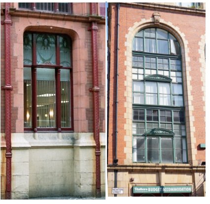
Industrial buildings often had many windows, or even unglazed openings (many industries benefited for copious ventilation), early forms of artificial light were feeble compared to daylight and cost money. Metal windows, made from cast iron and often cast to represent rather Gothic carved stone, were popular by the time the railways arrived. These were often disguised to look like carved stone, on the better examples it is necessary to use a magnet to check the true nature of the material. These were less common on industrial buildings but were sometimes used on the side of the factory offices facing the street. The example below left shows a typical cast iron window in a central Manchester office building, note also the decorative casting on the rainwater down pipes to either side. Cast iron windows could be made in modular sections (to ease transportation) and bolted together on site, the example shown below right consists of five separate units.
Fig ___ Cast iron windows
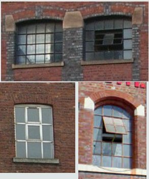
One of the most characteristic factory windows was a multi-pane metal framed design made from flat metal strip (wrought iron then later steel). These appeared in the later nineteenth century, the market leader in Britain being the firm of Crittal Windows Ltd of Braintree (owned by Norcros since 1968). They usually had a central section pivoted to open for ventilation, either hinged to rotate (below upper right) or hinged at the top edge (below lower right). The glazed panes are called 'lights' and the opening parts of a window are called 'opening lights'. Metal framed windows are galvanised and last many years in service and the thin frames allow a larger area of glass. The older multi-pane designs with the hinged section to allow ventilation are seldom specified for new buildings but the long life of this type of window means that a great many remain in place on industrial buildings in the early 21st century. The upper example in the photos below is (from memory) the more common industrial type, with a large central section hinged to tilt as shown for ventilation. The lower photos show a type with a top hinged section, as I remember it this was a much less common design on factories. The advantage of the top hinged type is that it is easy to model these if using clear glazing material with the frames printed on or added using paper strips, simply cut through three sides and bent the section outwards, this serves to add some relief to a large number of similar windows on a factory or mill wall.
Fig ___ Strip metal factory windows
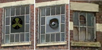
One advantage of the centre opening in these windows was the ease with which an extractor fan could be fitted. The illustration below shows an open fan type, popular with the spread of electricity supplies in the 1930s (left), a more modern encased fan fitted to a metal plate, typical of the type fitted from the 1960s to date (centre) and a glass pane with a circular hole which used to carry a small electric extractor fan. Adding one or two of these fans serves to break up a large expanse of factory buildings.
Electric extractor fans
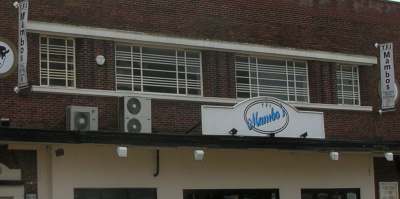
In the 1930s, with the popular Art Deco style of the 1920s and 1930s favouring the flat and light appearance of metal frames, they were widely used for domestic glazing. The name Art Deco derives from the 1925 Exposition Internationale des Arts Décoratifs in Paris and it was characterised by strong geometric shapes and the use of man-made materials. Domestic flat metal glazing was usually more complex than the regular squares of industrial windows, the example shown below is a flat above a shop in a flat roofed building.
Elaborate flat metal window frames on a flat
The Peco OO scale 'Shop and Flat' kit is the only commercial model I know of that features this type of window framing.
In the post war era council housing boom metal frame windows were extensively used in the offices, houses and blocks of flats being built to replace war damaged buildings. By the 1960s central heating was becoming more popular and the older type of metal frames began exhibiting a tendency to produce condensation and they were widely associated with council housing, which did little to endear them to the middle classes. Examples of domestic steel framed windows were still widely seen in council owned properties into the late 1970s.
By the mid 1970s the frame design had been changed to prevent condensation and draughts and double glazing was introduced but the recovery from the bad press the older types had received was a slow business as timber and UPVC windows were cheaper.
The industrial application of metal framed windows did not suffer from these changes in fashion and steel framed windows remain today a popular choice. On the industrial buildings a variation on the older window used a simple rectangular form with a large central pane as shown below. This type of window was fairly common on industrial buildings of the 1950s and may well have first appeared in the pre-war era. The car in the lower left gives the scale of these windows.
More modern metal framed window design
The long spans of industrial buildings brought a need for 'roof lights' (windows set into the roof itself) and these were common by the later nineteenth century. Up to the 1970s the top edge of the window was tucked under the slates or other roof covering and the bottom end sat on top of the slates below, allowing water to run off. More recent roof lights have often been made up of a frame sitting entirely on top of the roof clamped to an inner frame and relying on a good seal at the upper end to prevent water ingress. With the development of clear plastics and translucent fibreglass some buildings (usually with corrugated sheet metal roofs) have roof light consisting of clear or translucent panels.
Roof lights
The 'North Light' factory roof appeared at about the turn of the century and became common from the early 1930s. These roofs had windows on one side, usually the steeper side, all facing north to provide an even diffuse light. The window side was steep, anything from forty five degrees to vertical, the non widowed south facing side was at an easier angle, typically thirty degrees.
The north light roof is almost exclusively associated with industrial premises, the example shown below is a single storey structure, note how there is a flat strip of roof between each of the northlight sections to allow cleaning of the windows, this is a characteristic feature of northlight roofs although some more modern buildings actually opted for a wooden walkway on the facing slope. The flat area between the roof sections would be clad in either tarred felt or strip lead to waterproof it, to prevent the boots of the workmen punching holes in these materials it was common practice to add 'duck boards' strips of wood perhaps two inches wide with gaps of perhaps one inch laid on transverse strips as a walkway. The gaps are rather wide on this example, although the raised parapet is hiding the base of the valley, so they are not quite as wide as they seem.
Fig ___ North light roof on a single storey building
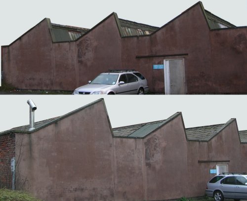
Not all north light roofs were the same however, on some the non-windowed side was curved sheets of corrugated iron or corrugated asbestos sheeting, but this was not terribly common. As with roof ventilators the north light windows became less common from the 1970s on as artificial lighting improved and the nature of the work done inside the buildings changed. In the photos below the building has had the north light windows removed and the north facing sections are clad in some form of rather thick modern tile.
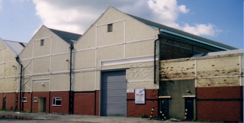
Fig ___ North light roof on a large factory building
North light roofs can be combined with other roof shapes to make a more interesting building, the photos below show the same building as in the photos above, this has a flat roofed structure facing the road with a rear extension bearing the north light roof. Note the drain pipes at the base of the troughs of the north light section, the drain on the main building shows the height of the roof at that point, although there seems to have been a water tank there originally and I believe that pipe is a later addition. Note also the colour of the concrete rendered wall around the works yard, a light greenish grey, this wall receives little or no sunlight.
Fig ___ Flat and north light roofs on a factory building
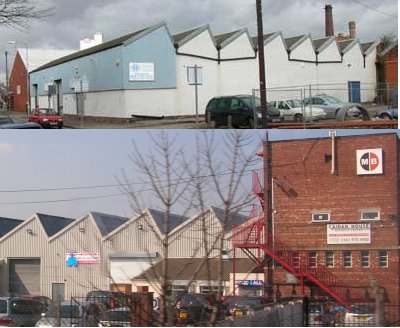
The North light roof was being added to factories built in the 1970s but seems to have fallen from favour since then, the photos below show two fairly modern (that is 1970s) factory buildings each having a north light roof section.
Fig ___ Post war factory buildings
One point to note if adding a north light roof to more than one building, the north light side should all point in the same direction. I have seen a few layouts using the old Graham Farish printed factory building kit where both the peel-and-stick sides have been used on a back scene but in close proximity, which is wrong.
Chimneys & Ventilators
Chimneys appeared in about the twelfth century but it took many years for the design to be understood. They were an important feature of all buildings in the days when coal powered everything. Even small huts would often be equipped with either a stone or brick fire place with associated chimney, or an iron stove with metal 'stovepipe' chimney. Earthenware chimney pots are only used on smaller chimneys, mainly domestic types. They first appeared in the Medieval period but only became widespread in the early nineteenth century. Local variations such two slates inclined together to prevent rain falling down the chimney probably arose at about the same time.
The metal stovepipe chimney is very easy to model and are worth adding to odd buildings in any industrial scene. The simple open pipe was a feature of many smaller buildings and huts, they were often seen sticking out of the roof of Nissen huts, either centrally or toward one end and off-centre. They are easy to make using a brass wire, florists wire or even an old broken sewing needle for the core. Remember to add a small square of light grey painted paper to the base as shown to represent the lead 'flashing' which keeps the rain out.
For the capped type find the finest panel pin you can, wash the top in thinners to remove all grease and add a blob of Milliput or Araldite to the top. Shape the putty or glue top represent a cone shape whilst still wet, you can sand it smooth when dry. Add the paper strip as before to make the stack. Again add the small square of paper to represent the flashing where it passes through the roof.
Fig ___ Stove pipe chimneys
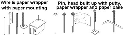
The 'pot bellied stove' was invented by the American Ben Franklin in the early eighteenth century and arrived in Britain shortly thereafter. A cooker cooks food but a stove also heats the room and the pot-belly design allowed you to cook easily on the top whilst the stove body and the metal chimney inside the building provided additional heating. This was much more efficient than the standard household open fire with a brick chimney but in Britain the iron piped stove was confined mainly to industrial premises. You might well see a 'stove pipe' extending through the roof of a small hut or the cabin of a boat or barge but houses and offices usually had brick or stone chimney stacks. The cooking range, a cast iron enclosed stove with an oven or two built-in, was patented in 1802 by an Englishman by the name of George Bodley and quickly replaced the open fire for cooking. The famous Aga stove arrived from Sweden in 1924. With all chimneys adding a smoke generator is an option but beware of heat warping plastic card roof or wall sections.
Prior to the 1940s large industrial chimneys were usually made of brick. Square-cut 'dressed' stone (technically called 'ashlar'), aside from being expensive and difficult to get into position on a large chimney, suffers from weather damage. Rough stone was only ever used in domestic or very minor industrial chimneys, it was normal to form this into a cylindrical stack to avoid jointing at the corners. Some chimneys had a reinforcing frame of iron or steel added to the outside. This can be represented using strips of paper tinted dark reddish brown.
Chimneys are tall but they are normally viewed from the ground where the angle has a foreshortening effect. We have all seen tall chimneys but due to this distortion correctly sized model chimneys, like correctly scaled trees, often look too tall. Chimneys are always taller than the buildings around them, this is important as they need the air blowing across the top the draw the gasses up the flue (there are some rare exceptions to this rule, but I suspect these do not function very well).
As a guide chimneys attached to mill engines were typically a hundred feet tall (two stories taller than the mill itself) and chimneys associated with processes producing noxious fumes could be up to three hundred feet tall.
The builders did not always get it right, some chimneys proved too short, more commonly they did not push the fumes high enough. One way to improve both these conditions was to add a tapered metal extension to the top as shown below left. As these chimneys grew old it was common practice to add a steel reinforcing framework to the outside, made of flat strips bolted together as shown below right.
Fig ___ Chimney with metal extension and another with an iron reinforcing frame.
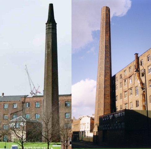
Both the chimney shown above was photographed at the former Dunlop G.R.G (General Rubber Goods) factory in Manchester (now re-built as designer micro-flats).
By the mid nineteenth century decorative chimneys were popular for factories, often styled to resemble bits of old Italian castles or including echoes of ancient Egypt.
Big chimneys were not usually built sticking out of the roof of the factory or mill, they required a solid foundation to take the weight and were as often as not mounted on a three foot high brick base adjacent to the engine house.
Having said which if you have a chimney in your 'bits box' that is too short for the building you wish to use it with you can mount it on top of a tower. Bliss & Sons Tweed Mill at Chipping Norton built in 1872 had its chimney rising from the centre of a dome atop a corner tower.
Fig ___ Sketch based on the Bliss & Sons Tweed Mill
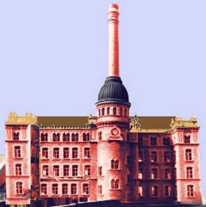
Some industrial processes required access to an open hearth or furnace located inside a workshop. Examples of this include glass works and forges in engineering works. On these there was sometimes a cowling arrangement built on the roof above the hearth, with a chimney extending from this. This looks difficult to model but in fact it is quite easy and certainly adds an industrial flavour to the building. The sketch shows such a structure seen in South Manchester a few years ago, the cowling on the prototype was corrugated metal but slate on rafters might also be seen. The chimney on the original was square in section and both the cowling and chimney were painted black. This design could be used in a range of industrial buildings, for example above the small forge at an engineering works.
If you try and cut the trapezoidal hole required in the roof you will get involved in some complicated trigonometry. The easy way is to make the shell of the pyramid from post card or thin plastic card as shown. First measure the side that will be at the bottom end when on the roof (1). Next measure the building, you need the height from the eves to the top of the roof (2) and the distance from the centreline to the edge (3). Make up a template from card (4) and fold this into a U shape as shown (5). Take a scrap of card or wire and ink this with marker pen, or anything that will leave a mark, oil would do. Place the card or wire on the template and allow it to touch the back side of the pyramid as shown (6). Mark the resulting line with care and then draw lines down the sides of the pyramid from this line to the opposite bottom edge. Cut away the parts (shown shaded) and your pyramid will sit square on the rooftop (7).
Fig ___ Chimney and associated cowling for open hearth works building
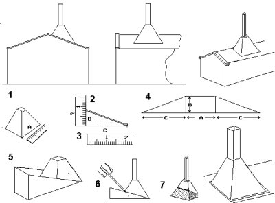
Modern chimneys are usually of concrete or metal construction, generally tall and slender. The metal types usually require some form of support, for shorter types this can be guy wires, for the taller types, often grouped together in combined stacks, a metal framework is added. One feature of many larger metal chimneys is a spiral of reinforcing on the upper section, usually about a quarter of the full height. Metal chimneys often have a silver body with the top couple of feet painted black.
Fig ___ Modern (post war) metal chimney
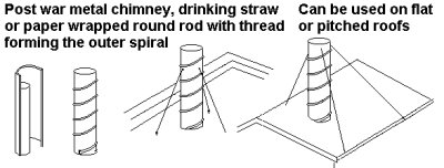
You may find a suitable thin-walled drinking strap (2 or 3 mm in diameter) but failing this resort to the paper wrapper method as shown. To represent the spiral winding of the prototype add a length of the finest fishing line you can find, glue this in place with Superglue or wipe the strand through a blob of Uhu before placing it on the chimney. The support wires are more lengths of the same fine fishing line passed through pin-holes in the tube. Pain the tube silver and the support lines light grey.
For a taller chimney, especially if the top is black, you could get away with Plastruct tube, although the walls are rather thick for this application. In that case a strip of 10x10 thou could be used for the spiral.
Some buildings such as the Hoffman brick kilns discussed in the section on Ancillary Structures were built round a central chimney.
The sketch below is taken from a mid nineteenth century drawing of a glass works. There were several such buildings in the works, along with a number of one and two storey structures and all enclosed by a high brick wall. The associated illustrations showed a range of processes in similar buildings including the manufacture of plate glass.
The chimney is above the central hearth where the glass blowers worked.
Note the 'dormer windows' in the roof, these were unglazed openings to allow ventilation, when operating the large doors would probably be open to allow better ventilation as well.
Fig ___ Glass works building.

Where there was a risk of glowing embers being blown out of the chimney it was normal to fit a spark arrester. In its most basic form this could be a simple metal mesh designed to catch the embers but in many instances there was enough material being blown through to warrant some method of catching it. The standard technique was to add a section of tubing which widened out then closed in again. As the hot gasses entered this tube they slowed down and the cinders or what have you fell out of the air stream and collected in the base. The constriction near the top increased the speed of the gasses again, causing them to be blown higher into the air. The most familiar application of this kind of chimney is the classic American wood burning steam locomotive but they were used in a range of industrial applications including producer and water gas plant.
Fig ___ Spark arresters
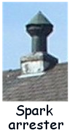
Ventilation was only really considered scientifically in the eighteenth century when the British scientist Stephen Hales (1677-1761) made a long term study of the role of water and air in supporting life. Hales designed a ventilation system which was installed on slave ships, hospitals and other places where people were crowded together and this greatly reduced the mortality rates in these places.
Factory ventilation systems must remove hazardous airborne contaminants from the workplace. Nearly all chemical processes generate hazardous waste gases and vapours, and these must be removed from the workplace environment in a cost-effective manner. Chemical engineers, in particular, are involved in ventilation design for factories and refineries.
The degree of ventilation required is governed by the activity taking place inside, so a glass works or iron foundry would have large vents whilst a tobacco warehouse would have almost none. As a general rule for adequate ventilation the air in a room should be changed completely from one and a half to three times each hour. Put another way about 280 to 850 litres (about 10 to 30 cu ft) of outside air per minute needs to be supplied for each person.
Buildings which contained forges and the like often had lots of ventilation, often simply by providing un-glazed openings in the walls. These took various forms but the two most common were the simple circular hole in the gable end and in taller buildings large semi-circular opening in the side walls. The latter was a feature of several gas works retort houses.
There were a number of roof ventilator designs seen on industrial buildings from the early nineteenth century onwards, louvered openings were very common, often in ridge line extensions as below top right. The flat roofed building in the sketch below bottom left is loosely based on the British Screw Company works at Leeds, built in 1892. The word clerestory is a contraction of 'clear storey', an empty space added to the top of a building (or indeed a railway coach) to improve ventilation.
Fig ___ Ventilation on industrial buildings
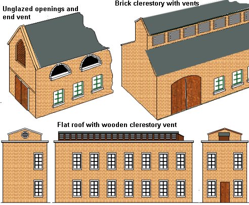
Roof-top ventilators add interest to any roof, they were a feature of many industrial buildings and came in a great number of designs. The Peco Engine shed kit comes with a long louvered roof vent and for some reason the kit also includes two smaller vents (and a spare set of doors with a curved top), all very handy. The example below shows a wooden vent on top of a former railway workshop, this type of vent was fairly common on industrial buildings but I would doubt any building have been built with these since the early 1950s as powered ventilation systems have become the norm.
Fig ___ Wooden roof vent at Stockport
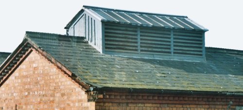
Not all louvered vents were so large, smaller square types (known as beehive ventilators), were common. The photographs below show, from the left, a simple beehive type vent, a powered vent dating (I believe) from the 1950s (this seems to have replaced a simple wooden 'beehive' type as it is sitting on a rectangular base), a modern industrial vent exhaust and two ventilators on civic buildings dating from the later 19th century, some industrial buildings had similarly ornate roof ventilators.
Fig ___ Photos of roof mounted ventilators
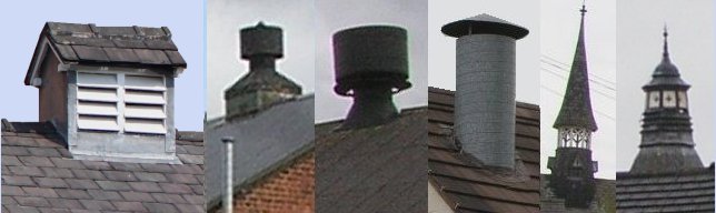
The older metal vents were (from memory) always painted black but in 2007 I noted an example where they have a light gray stem with a light blue cowling. This made the factory resemble a dairy but I was not able to check its actual purpose and I think it was some kind of engineering works.
Fig ___ Modern roof vents in 2007
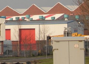
You can make your own roof ventilators of course, making your model a little different is useful for exhibitions. The drawings below show a series of the more common ventilator types, the upper drawing is for a curious design which I have seen on several old industrial buildings in the North West and in London. These vents were typically three or four feet wide by about four feet high at the opening and were protected by a louver to prevent rain getting in.
The electric fan type seen since the mid 1930s usually had a coned central housing for the fan. This can be made by filing the head of a wood-screw to the required shape and adding either a paper wrapper or a length of thin-walled drinking straw. The standard straw available these days is plastic and typically 5 mm in diameter, which is perfect for these vents.
If you do not fancy your chances at filing a wood screw an alternative method is to roll a strip of cigarette paper round a pin then draw the pin up to pull it into a cone as shown in Fig ___ (xxx). You need a saucer of water and PVA wood glue to hand, once the shape is right give it a wash with the mixture and it should set solid. Cut off the head of the pin and either add a paper wrapper or length of drinking straw to complete the top assembly.
The lower part of the pin can then be inserted through a short length of old 'Biro' tube to form the supporting duct, the pin itself will extend through the rood and can be secured with Milliput on the inside.
Some of these cylindrical vents had a circular plate top, for this use a length of drinking straw 3 mm long, take a nail with a head which will fit inside the straw and pack the base of the straw onto the nail head with Milliput. While the putty is still wet insert four lengths of guitar E string or any suitable rod close by the sides. The top can be cut from 10 thou plastic card using a paper hole punch and glued to the supports with Superglue.
The modern 'mushroom' ventilator appeared in the 1960s, industrial versions usually have a short length of supporting ducting and a motor mounted externally on top. Not all such ventilators have the top mounted motor and this can be omitted if required and they are often painted in light colours rather than black.
These modern vents can be made using a small wood screw with a dome (not counter-sunk) head anything from four to eight millimetres in diameter. File the top of the head flat and if there is any slot left fill this with Milliput. The Milliput slot can be used to hold a short length of guitar E string bent into an L shape which will support the 'motor'. The motor itself is a length of 'Biro' tube with the head of a pin stuck on top. You can use cheese-headed bolts for this, simply bevel the sides with a file, fill the slot with Milliput and add the motor as above. This leaves you with a thread on the shank, you can file this off, fill it with Milliput or simply add a paper wrapper.
Fig ___ Roof Top Ventilators
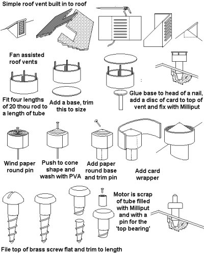
Note that small electrically powered roof vents were often a later addition to the building. In this case they would not be mounted on the ridge line itself but would be off-set slightly to one side.
The example below has several features of interest, the window shape suggests the use of cast iron windows, most now bricked up. There is a circular opening for a ventilator on one side of the building, and two roof vents on the ridge line of each half. A modern addition is the number of silver metal chimneys visible on the building end. The group of three small windows toward the centre probably indicates the position of the workers lavatories inside the building, their position indicating that there was a ground floor below, accessed via large doors at street level, with the working floor above this. The roof span is very large however I was not able to gain access to inspect the interior. Note that the larger windows cross the baseline of the roof apex, I would suggest this building probably employs steel trussing and cross girders to support such a wide span of roof.
Fig ___ Factory building with roof and end vent in 2007
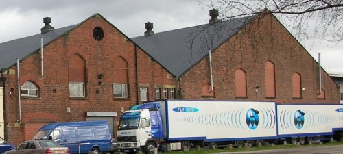
Iron foundries, glass works and the like tend to have large doors which are often left open and they have a healthy draft of air drawn through by the heat of the furnace. All that is required in a foundry is some roof ventilators but buildings used for light engineering often require forced drafts using mechanical fans to augment the natural flow of air.
External fire escapes
External fire escapes appeared in the UK in about 1890. One common early design was a spiral staircase set up beside the building but the most common type was a series of platforms connected with diagonal ladders and as they were standard and readily available they were often added to the design of new buildings. In areas where controlled access was an issue the last section might be a vertical ladder counterweighted to lower itself if anyone stepped onto it, or a length of stair case similarly counterweighted to lower to the ground with the weight of a person. External fire escapes were even added to hospitals, although these tended to have a more gentle slope to the stairs and the stairs extended down to ground level.
Fig ___ Typical external industrial fire escapes
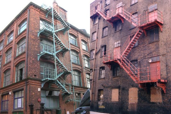
Note the metal windows and modern vents set into the window under the fire escape.
You can use Plastruct stairs and hand rails, unfortunately the much more economical ABS type seem to be unavailable at the moment so you are restricted to the more expensive polystyrene 'Fineline' version.
External fire escapes continued to be incorporated on new buildings into the 1960s, some of the larger designs built from the 1960s on used concrete rather than metal (these tended to be built separate from the building with a central supporting spine). Fire escapes on the outside of buildings became unpopular in the 1970s however, notably after a news photographer in the USA caught pictures of people falling from a broken escape, and they ceased to be incorporated in new buildings. Existing escapes remained in place however, the rules require two separate fire exits and where the design of a building precludes this the old escape remains a requirement.
Temporary Buildings
Temporary buildings have until recently been generally crude and extremely 'rustic'. The navigators digging the canals and later building the railways lived in simple shelters half buried in the ground and resembling World War One trench dug-outs.
By the early nineteenth century planned deployment of personnel, be it in the field of battle or to a large construction job, usually entailed the use of large numbers of canvass tents. These could be rolled up and moved from place to place but offered the occupants little protection from the weather.
When a more commodious building was required a carpenter would be called in who would order up the timber and, given time, a decent 'hut' could be built. Windows were seldom added, if they were required the glazier had to liaise with the carpenter to make suitable frames. Having put this much work into the thing the original 'temporary' building might remain in place for years or even decades.
With the development of the railways a new source of quick buildings appeared in the form of redundant goods van and coach bodies. The former became relatively commonplace in farm yards, factories and of course alongside the railway itself. Again windows were seldom added but the body was usually supported on rows of bricks or old railway sleepers to prevent damp rising up and rotting the floor. Van bodies proved a useful size, about seventeen feet long, eight feet wide and six to seven feet headroom. They were used in a wide range of applications including stables for up to two horses, stores and even occasionally for buildings such as road-side cafes. These structures proved very long lived, examples of pre-grouping (pre-1923) van bodies were being found in the 1980s and purchased for restoration to their original function on preserved railways.
The redundant railway coach bodies were used by the railways to build 'mess huts' for the staff to eat in and quite a few ended up as cottages, cafes & etc. The big problem with both these items was that they had to be transported by road lorry (except where they were used on the railway property), and being heavy they needed a crane to lift them into position.
Fig ___ Grounded Railway Van and Coach Bodies
XXX modelling the various options
World War One brought mass-mobilisation and the troops in the fields of France soon found the tents to be pretty useless. In 1916 Peter Nissen (an officer in the Royal Engineers) devised the Nissen Hut, a simple wooden framework covered with curved panels of corrugated iron sheet which reached down to floor level (in effect a curved gable ended roof with no walls). The standard size was twenty seven feet long by fifteen feet wide and on the original design the ends were also made of corrugated iron, with a window in one and a door in the other. These huts could be shipped in 'kit form' and took only a few hours to erect. They had a planked wooden floor and an iron stove was normally fitted somewhere about the middle with its black pipe sticking out through a hole in the roof. The floor was raised slightly above ground level and the sides were often supported on low brick walls, typically twelve inches high. Although they were little more than iron tents and had no insulation the Nissen huts proved a great success. Nissen set up a company to manufacture the huts after the war, they were often then used for more permanent structures with brick ends and in a few cases windows were added to the sides as well. By the 1920s there were three standard sizes of Nissen hut, sixteen, twenty four and thirty feet across the base, all built in six foot long sections. As many sections as required could be bolted together to produce a hut of the required length and the simple design left the inside virtually clear of obstructions making it ideal for industry.
The military subsequently developed a variation on the Nissen hut called the Romney hut, which had a tubular metal inner frame. This was thirty five feet across the base and was supplied in multiples of eight foot lengths.
Amera Plastic Mouldings offer a military late model hut with side windows in 1:72nd scale but the plain sided type can be built easily enough, personally I recommend wrapping some Bacofoil round a tube of the required diameter (32, 49, 61, or 72 mm for British N), add a wrapper of good quality cartridge paper over that and then wind thread (for N gauge) or string (for OO gauge) round this. Coat the lot with a varnish (shellac is good) or watered down PVA glue and leave to dry. Once the glue has set use the end of a steel ruler or a blunt wood working chisel to press-in some horizontal lines (this is optional). The tube can then be slipped off the former and cut in half to provide two huts, the Bacofoil prevents it sticking to the former. The former is then used to mark out the material for the ends; 1mm scribed card for planking, embossed brick plastic card or plain card and brick paper. The example shown is 4mm scale, it forms part of a military 'base', the former was a 2ltr plastic drinks bottle and I used thin string for the corrugated metal and 'lollipop' sticks for the ends.
Fig ___ My model Nissen type hut
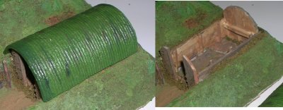
The Nissen hut soon became a mainstay of temporary building design, it remained a military mainstay throughout the Second World War and war-surplus equipment filtered into civilian life in considerable quantities. Often these buildings have proved a lot less temporary than intended and examples remain in use today. I am informed that a firm in Yorkshire was still building and selling the standard Nissen huts in the late 1990s. The example shown below was in use as a domestic garage in South Manchester in 2007. This building has ends which appear to be 'asbestos cement' panels on a light wooden framework (a popular choice for domestic garages up to the 1970s), the door is actually quite low, perhaps five feet high (note the garden chairs by the side of the building).
Fig ___ Nissen hut garage
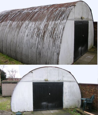
Fig ___ Large corrugated iron industrial building
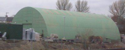
Following the Second World War a British Project Manager called Donald Shepherd was put in charge of a large construction project. When he arrived on the site there was nothing in place and he found himself having to work with drawings spread on packing cases in the open whilst he ordered up the timber, glazing, felt roofing material and electrical fittings with which to build a site office. He gave the problem some thought and came up with the idea of the Portakabin. The first production design appeared on the market in 1961, eight foot square by sixteen feet long with two metal tubes on each side. These tubes were the key to the design's success; they contained the extending legs which meant the unit could be unloaded from a flat-bed lorry without requiring a crane and allowed the body to be supported clear of the ground once in position. The legs also allow the cabins to be stacked one atop another to provide a two-story building, this requires an external staircase to reach the door on the upper cabin which makes it a fiddly job to model.
Fig ___ Portacabin
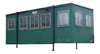
There is a one-piece cast model of a small Portakabin in the Graham Avis range of trackside details and, for layouts set in more recent times, there are etched kits of a twenty foot and thirty foot modern Portakabins in the BH Enterprises range (68 Meadow Road, Garston, Hertfordshire WD2 6JA). The etched kits require glazing and jacking supports to be added by the modeller but both jobs are simple enough two larger cabins (one thirty foot long and one forty foot long. You could build your own of course, personally I would probably opt to make it using a postcard wrapper for a length of strip-wood for the body with the windows cut out using a modelling knife or single edged razor blade and square ends cut with fold-in-and-glue tabs from the same material. Glazing would need to be strips of clear plastic card but this could be secured to the insides by adding a little Milliput behind it top and bottom.
____________________________________________
^
Go to top of page