Road Traffic - Introduction, Licensing, Wheels, Suspension, Brakes and Transmission
Major contributions to this section have been made by Ian Mackay, Rob Batten and Ian Franz, all of whom know far more about this subject than I do.
The lack of roads has meant that wheeled vehicles were until fairly recently little used in practice. Regarding passenger transport the Romans were impressed by British war chariots but the poor quality of the roads after the Romans departed meant that most people preferred to be carried in a box suspended between two horses called a horse litter. On the goods side the earliest record of a British cart is a drawing made in about 1100 AD. Most goods travelled on pack horses, each carrying about two and a half hundredweight (about 127 Kg). Pack horses require only a track to follow, they remained common into the 1750's and continued in use in remote areas, particularly the North West, until the late 1870's.
By this time the railways were established and steam powered road vehicles were providing regular services. The horse coach operators, river and canal 'navigation' companies and the various railway companies pressed for restrictions on powered road vehicles. In 1832 the government began levying high taxes on steam road vehicles and in 1861 the Locomotives Act limited speeds on the open road to ten miles per hour (16 kph) and speeds in town to five miles per hour (8 kph). The most memorable Act was that of 1865 which limited the speed of all types of mechanical road engines in towns to four miles per hour (6.5 kph) and required that they have a crew of three, one of whom had to walk in front carrying a red flag. These laws and levies greatly restricted the development of road transport in Britain, on the Continent there was no such restriction and road transport developed more quickly.
When the 'red flag' act was repealed in 1896 the speed limit was raised to 14 mph (22.5 kph), the annual London to Brighton car rally celebrates this event, known to motoring buffs as 'Emancipation Day'. The repeal of the 'red flag act' also brought in other legislation, a requirement for lights and some form of 'audible warning device' to be carried on all road vehicles and oddly enough it also required all motor vehicles to be fitted with brakes, although why that had to be put into a law is not clear.
From 1933 road vehicles had to be licensed to operate. Road haulage firms had to apply for a licence for each vehicle and there were three types in use; the A licence allowed the owner to hire out his vehicle but not to carry his own goods, the B licence allowed the owner to either hire the vehicle out or use it for his own goods and the C licence allowed the owner to carry only his own goods. Farmers could apply for an F licence, allowing them to move their own produce (or that of neighbouring farms) using their tractor to haul a trailer, after the second world war tractors increased in power and farmers could use low-tax fuel so this practice became more commonplace. It would therefore be quite possible to see a farm tractor hauling a trailer in a rural goods yard right into the later 1950s.
Many of the more visible changes to road traffic were brought about by legislation, for example the act of 1898 repealing the need for a man with a red flag to walk in front of a motor vehicle also introduced a requirement for lights and some form of 'audible warning device' to be carried on all road vehicles (and oddly enough it also required all motor vehicles to be fitted with brakes, although why that had to be put into a law is not clear). In 1903 it was decided that, given the number of accidents and the difficulty in tracing the perpetrators, some form of licence would be required both for the vehicle and for the driver. The visible change this brought about was the introduction of the number plate.
Number plates
For a detailed history of the subject see National Numbers - History, a website operated by a company dealing in number plates.
Number plates appeared in 1903 when motor vehicles and drivers both had to be licensed (renewable annually) by their local county council. Early plates had a single letter followed by up to three numbers (A1 was issued in London in 1903), number plates were painted black with white lettering and were usually bolted to the front and rear bumpers of the vehicle. The introduction of number plates was soon followed by special 'trade plates' which were licensed to dealers to allow them to drive unregistered vehicles on the roads for delivery purposes. Trade plates are similar to number plates but have a triangular extension on the top in which a special licence is displayed. In the mid 1930s some councils had used up all the two letter and four number options and changed to three letters with three numbers and in the mid 1950s some councils had to reverse the order making it three numbers and three letters.
Front number plates were always a long rectangle with a single line of lettering but by the later 1930s rear number plates were often square with two rows of lettering. By the 1940s a light was required on the rear number plate (not on the front one), this was typically a small black block on the top edge of the rear plate.
In 1963 a suffix letter indicating the year of registration was introduced, by this time most cars were built with a recess for the number plate and they were single line oblongs front and rear. In 1973 the appearance of registration plates was changed to reflective plates black on white at the front and black on yellow at the rear. In 1975 the front number plate on motorcycles and scooters was abolished for safety reasons.
A brand new format for registration numbers was introduced in 2001, the new numbers have two letters (indicating the area), two numbers (indicating the year) and three more (random) letters. For the first time the letter Z is allowed (in the final three letters).
GB Plates
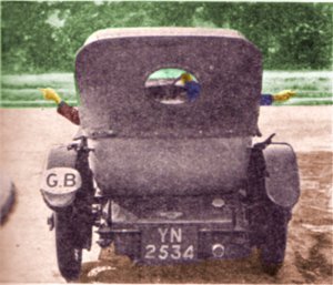
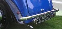
The system of oval plates mounted on the rear bumper of the car indicating the nationality of the vehicle was introduced in about 1910 and the UK was one of the first countries to adopt the plates. By the later 1920s virtually all of Europe was using them and countries as far afield as Egypt had adopted them as well. These plates were not a common sight prior to the 1970s and were normally associated with the more expensive cars. The example below is from a photo taken in 1934, the photo accompanied a stern warning about passengers gesturing out of the window when approaching a junction (the intended turning direction, and indeed slowing down, were indicated by hand signals at this time).
GB plate in 1934
The British plates, up to the 1950s or 1960s, were oval in shape and 7 inches (18cm) by 5 inches (12.5cm) in size. Early plates (as shown above) were white with black markings but those I remember from the 1950s were black with white markings and a white rim, actually the plates were embossed metal with the raised lettering and rim in bare metal (if I remember correctly). These were bolted onto the front and rear bumper of the car. These changed to a thin flat metal white oval plate with black GB and no rim, again usually bolted to the bumpers, and these were replaced in the 1970s with the stick-on type (by which time the traditional but largely useless metal bumper bars were no longer fitted to many cars).
GB plates and stickers
By the 1990s international travel, especially in mainland Europe, had grown to the point where this old marking was considered obsolete and the plan is to replace the oval plate (now usually a sticker) with a marking on the number plate of the vehicle (which will be both on the front and rear plates). This EU policy (widely known as the Euro-plate) has now been adopted by several non EU countries as well and as of 2004 plates with these markings are already commonplace. They are not universal however, not everyone wants the GB on the number plate, the example shown below right of a stick-on version EU GB plate was photographed in 2007.
GB numberplate and a GB sticker photographed in 2007
Wheels and Tyres
Well into the early twentieth century the most common tyre for road vehicles was the steel hoop mounted on the spoked wooden wheel. Horse drawn waggons generally had tyres about two to three inches wide, waggons intended for work in winter or on muddy ground had much wider wheels, the metal tyres used on horse drawn manure waggons were typically five inches wide.
The spoked wooden wheel used oak for the spokes and a softer wood for the rim and the hub. The army used something called the 'artillery' wheel in which the spokes were bolted to a heavy steel hub rather than fitted in as the wheel was built. This design, originally used for field artillery, was easier to maintain than the traditional design and although heavy it was also widely adopted by the railways for use on their horse drawn vehicles (and on some early motor vehicles).
Rubber had been named in 1788 when a British chemist called Joseph Priestly discovered that a crude form, obtained by coagulating latex, could be used to erase pencil marks by rubbing. Vulcanising of rubber (heat treatment with sulphur to produce a hard wearing material) was invented by the American Mr Goodyear in about 1839.
Rubber tyres and the principle of the pneumatic tyre were patented by an Englishman called Robert William Thompson in 1845 but no one showed any interest in his idea. The first practical pneumatic tyre was patented in 1888 by the Irish vet and inventor John Boyd Dunlop (1840-1921). He developed the tyre for his son's bicycle and soon began marketing adult tricycles equipped with pneumatic tires. Dunlop sold the patent to William H. Du Cros, who in 1889 set up what became the present day Dunlop Rubber Co.
Dunlop's design was not removable so fixing punctures took a lot of work. The French Michelin brothers developed the removable rubber pneumatic bicycle tyre in the 1880's but it was the end of the decade before they became popular. Pneumatic tyres became standard on bicycles but it would be another fifty years before they became the norm for vehicles carrying heavy loads.
Steam powered road wagons initially used steel tyres, giving way to solid rubber in the years before the First World War (plain steel was very liable to slipping on wet cobble stones, resulting in numerous accidents). Even quite small lorries retained solid rubber tyres, only finally changing to pneumatics in the later 1920's. The first buses with pneumatic tyres (and also featuring a covered top deck) appeared in about 1925.
Early tyres were canvas tubes with a coating of rubber, by the 1930s cord was added to the tyre making them rather more robust, but in a world where horse were still common horseshoe nails on the roads remained a major source of punctures. In 1948 the French company Michelin introduced the radial-ply tyre and the American firm Goodrich produced the tubeless tyre. In 1972 Dunlop introduced safety tyres, which seal themselves after a puncture and there are several designs of wheel, generally known as 'run flat' which allow the car to be driven at speed with a deflated tyre, although these are not standard fitting on most cars.
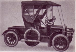
Early pneumatic tyres were very narrow, wide 'balloon' tyres resembling those seen today appeared on lighter vehicles in the later 1920's but the older style narrow tyres remained in use well into the 1930's. Early road vehicles did not have removable wheels, that feature only appeared after the First World War, so early vehicles carried a curious 'spare wheel', resembling a spare tyre but fitted with a steel rim, usually strapped to the side of the vehicle. These were bolted on to the outside of the damaged wheel and served to get one home or to a garage.
Singer car (1904) showing the early type of spare wheel
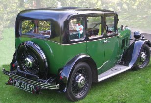
On the more up market cars it was common to see two of these 'spare wheels' bolted together mounted on the side of the passenger compartment. When complete spare wheels were introduced they were usually mounted on the side of commercial vehicles, often inside a protective casing. In the 1940's the modern practice of mounting the spare wheel under the rear of the rear platform of commercial vehicles appeared and soon replaced the side mounted approach. On motor cars the spare wheel was also mounted in a fairing on the side but as British cars tended to be small the favoured position was on the outside of the boot at the rear.
1930 Morris 6 with rear mounted spare wheel
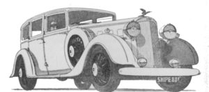
Having said which larger British built cars still had them on the side as shown below well into the 1930s.
1934 Humber Snipe 80 from an advert of the time
It was the 1950s before motor car spare wheels were commonly carried inside in a recess in the floor of the luggage compartment or 'boot' at the rear of the vehicle. The term boot comes from the horse drawn coach where the driver sat outside, the frame providing a foot rest was also used to carry valuable goods in a sturdy chest and the term carried over to motor cars. In America where the prime function of this space was to carry a trunk they adopted the word trunk for the space itself.
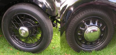
Early wheels on motor vehicles used either bicycle spokes or heavy metal spokes, similar to those seen on railway wagons of the time. The pressed metal 'dish' wheel appeared in the later 1920s, these often had D shaped holes cut around the edge to reduce weight. By the later 1930s the metal dish wheel was the norm for both cars and heavier vehicles. Cars were then fitted with chromed hub-caps to hide the 'ugly' metal dish.
Spoked and pressed steel motor car wheels
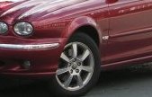
The snag with this type of wheel, mounted on an axle, was the 'unsprung weight', basically the more weight a vehicle has outboard of the suspension the more difficult it is to control. The solution, developed for high performance racing cars, was the Mag Alloy (magnesium alloy) wheel, which in place of the pressed metal dish has a set of thick but light weight spokes, usually coloured silver. This reduces the unsprung weight and also allows more air to reach the brakes, preventing them overheating. Mag-alloy wheels appeared on road cars in the in the 1970s, firstly on the more 'sporty' cars of the time such as the MGB-GTs and MG Midget and later on volume production cars when they were fitted to the Ford Capri. By the later 1990s these wheels were also appearing on the more sedate family saloon cars, which by this time offered higher performance that the sports cars of the 1970s.
Mag alloy wheels on a Jaguar saloon car
Modelling wheels is generally regarded as one of the more difficult aspects of our hobby. The spoked wooden wheels used on horse drawn vehicles are particularly difficult, fortunately however there are plenty of commercial models available which offer suitable wheels and also shafts for the horses.
Smaller rubber-tyred wheels used on heavier commercial vehicles can be a problem, one option here is to use the road wheels from an OO military tank kit. The German Panzer III and its variants have the best such wheels, the military kit market is depressed at the moment but models are re-introduced cyclically and two to look out for are the Matchbox Pz III tank and the Airfix Pz III Ausf G self propelled gun.
For lorries and larger horse drawn vehicles on layouts set at any time after the mid 1930's you can use one of the commercially available sets of lorry wheels. I like the plastic kind sold by Dornplas and the associated Dornaplas lorry models are sufficiently economical that you might consider using the chassis as the basis of a scratch-built model.
Small wheels as used on motor cars, milk floats and the like are less easy to find. The full size wheels are about fourteen or fifteen inches in diameter, which is just under two and a half millimetres in N. If you or anyone you know is replacing the Mercedes motor cars on a Lima articulated car transporter the wheels from the Merc's would do nicely, alternatively the Airfix Churchill Tank kit supplied 48 small wheels which will serve for this type of vehicle (other kits do not provide the separate wheels so look for the original Airfix kit).
The best option for modelling such wheels is to use short lengths of electrical insulation or empty 'Biro' tube, pack these with a little Milliput and add a stub-axle from brass wire. Whilst the putty is wet you can smooth it over with the tip of a moistened finger, this gives a clear demarcation between the putty and the 'tyre'. Stand the wheel on a scrap of cling film, preferably with a trace of grease on it (butter would do fine), and set aside to dry. When set the stub axle can be secured to the vehicle with a small blob of Milliput but Araldite is probably easier to use for this job.
Caterpillar tracks The original work on caterpillar tracks for vehicles was done by the Yorkshire inventor Sir George Cayley in the nineteenth century. In 1900 an American by the name of Benjamin Holt developed the first practical caterpillar track and soon there were several steam and petrol powered caterpillar vehicles on the market. The original Holt agricultural/artillery tractor was a steam traction engine with wheels at the front and tracks to the rear, it proved its worth in the First World War towing large howitzers about the battlefield. These vehicles had cross-country performance far superior to wheeled vehicles and they were mainly designed for agricultural use.
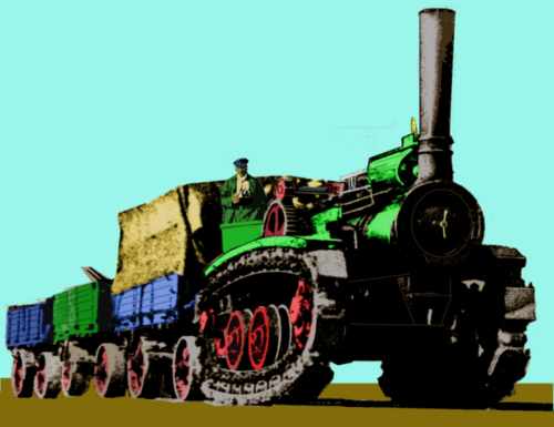
British firms such as Hornsby & Ruston produced tracked vehicles for agricultural use many of which were used during World War One for artillery towing and similar duties. The Ruston Horsnby design was a fully tracked vehicle, these had been built for use in the Yukon gold rush where they towed supplies up to the mining camps on trains of large trailers. The sketch below is based on a photograph of a Ruston engine undergoing trials shortly before the First World War,
Ruston tractor
In the late 1920's people tried using caterpillar tracks in place of the rear wheels on petrol lorries to produce the 'half track' vehicle. This was easier to control as it was driven much like a lorry, but the tracks on the rear were better able to carry loads over soft or rough ground.
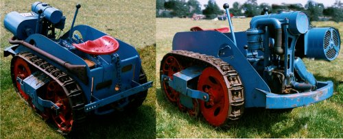
In the later 1930s small tractors fitted with caterpillar tracks were used for farm work, the example below is the smallest type I have seen, it was photographed at a show in 2004. I remember similar tractors (slightly larger and mass produced for the military in World War Two) being used on farms in Cheshire into the 1960s.
Small agricultural crawler tractor
There is a photo of a larger version of this type of machine in the section on Wagon Loads and Materials Handling - Road Vehicles and Farm Machinery
Modelling caterpillar tracks is not as easy as we might have liked. There are two main types, those with a single row of wheels with the track wrapped round them and those with smaller wheels at the bottom and 'return rollers' at the top. For slow-speed vehicles with low ground clearance such as crawler cranes the former type was preferred. These can be modelled using short lengths of plastic rod about 2mm in diameter. Glue these in a row and add a strip of paper to represent the track .
Where higher ground clearance and/ or speeds were needed one option was to use a single row of larger diameter wheels but these were rare on commercial tracked vehicles. A more common arrangement used a set of road rollers on a separate assembly shaped like an inverted T, the drive sprocket and return roller(s) were then mounted above this and the track wrapped round them.
Military Vehicles
The army has made great use of railway transport, and continues to do so today. Up to the First World War heavy kit such as guns were regularly moved but troops in the field were supplied by the horse drawn 'general service wagon', and numbers of these were regularly moved on rakes of bogie flat wagons. The railway wagons used were standard plate wagons, they did not need to be purpose built for the work.
The first tank, an armour plated vehicle running on large wheels equipped with hinged 'feet' was developed by a British inventor by the name of Roberts in 1908, he called it the Pedrail. The army did not take up the idea at the time but as the First World War settled sown into trench warfare, and the power of the machine gun became apparent, the British went back to Mr. Robert's idea for an armoured vehicle capable of crossing rough ground and produced the first military tanks. These used caterpillar type tracks rather than the 'pedrail's big wheels with feet and used a rear mounted pair of wheels for steering. Tanks were first used by the British in 1917, in spite of being only partially bullet proof and mechanically somewhat unreliable they proved to be the answer to trench warfare and the idea was soon taken up by the French and German armies. Tanks could not cover much ground, and broke down quite often, so they were moved for longer distances by rail. To carry these the British produced a heavy bogie vehicle called a Rectank, with big stabilising jacks built into the ends so the tanks could be driven along a row of wagons in a siding. The World War One 'lozenge' shaped tanks continued in use into the 1920s and the rectanks continued in use after that moving all manner of military vehicles.
Half-tracks remained popular with military forces into the 1950's but developments in control and steering systems saw a shift to fully tracked military vehicles in the 1970's. By the later 1990s there had been another shift with multi-wheeled vehicles being developed to replace many of the tracked military vehicles, the main advantage is that a land mine blowing one or two wheels of will not stop the vehicle whereas blowing a track off a caterpillar tracked vehicle will stop it dead.
Hydraulic and Pneumatic Propulsion
Pneumatic propulsion has been used in a variety of ways, on the continent and in America there have been numerous compressed air powered locomotives used in mines since the 1870's but the idea did not catch on in Britain. On the surface there have been several attempts to use air pressure to drive railways, the first seems to have been an Irish line in the early 1840's followed by a line from London to Croydon (1846-47) but probably the best known in Britain was the South Devon Railway of the 1840's. The line had a tube running along between the tracks, there was a slot along the top of the tube sealed by a leather flap and pumping stations at intervals extracted the air from the pipe. The coach or wagon had a piston secured beneath the chassis which ran along the tube and air was allowed into one end of the tube to drive the vehicle or vehicles along. The system performed well in service, speeds were high, gradients were coped with easily and of course there was no smoke and little noise. Unfortunately the technology of the time was not up to the job and the leather seal on the pipe gave endless problems. The railway was converted to normal steam hauled operation in 1848 and it soon became apparent that steam engines hauling heavy coaches were having problems on the steep gradients which had posed no problem to the light weight atmospheric vehicles. A variation on this idea was to build a 'tube' type underground railway in which the coaches function as pistons and this was tried in the late nineteenth century but did not catch on.
In the early part of the twentieth century several tram engines were built powered by compressed air carried in cylinders. These found some favour as steam engines for use on trams had by law to 'consume their own smoke' (the exhaust steam was typically run into the water tank to condense the steam, although one design had a roof mounted radiator system as a condenser). This added complexity and hence cost of the basic steam engine, hence the interest in compressed air. In the event the development of trams using overhead electrical pick-up provided a better solution to the problem.
Hydraulic power has been used on the railways only as a means of coupling a petrol or diesel engine to the locomotive wheels, this is called hydraulic transmission. Hydraulic transmission offers a better power to weight ratio than the more common diesel-electric systems used on locomotives. In the 1950's and 1960's Western Region of British Rail built several classes of diesel-hydraulic locomotive, most of which were successful although their maintenance costs were higher. When using hydraulic transmission there is no risk of electrical sparking so it is safer for use in areas where fire might be a hazard such as oil refineries and is often used for small industrial railway locomotives and lorries.
One quite common machine since the 1970's is the road-rail lorry with diesel hydraulic transmission, which can be used to move railway vehicles as well as for general haulage duties in a refinery or similar establishment.
Suspension Systems
Note - Motorcycle suspension systems were highly visible, these are discussed App One - Set Dressing - Private Motoring - Motorbikes, Scooters and Cars
In the seventeenth century someone in France tried suspending the body of a horse drawn carriage on leather straps but the swinging ride tended to make people sick. Spring suspension using metal springs between the chassis and the leather straps appeared in 1665 but this was not a great success at the time. As metal technology improved long 'Cee springs' were developed, as the name suggests these were C shaped, the lower end secured to the chassis and the upper to the body of the vehicle. The Cee spring caused the body to sit very high so carriages were prone to overturning.
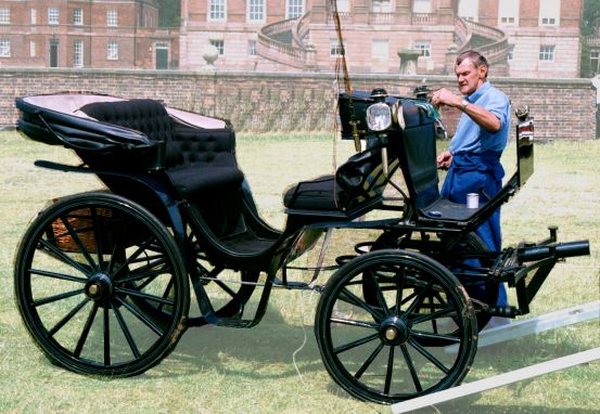
The key breakthrough was the development of the 'elliptical spring' by Obadiah Elliott in 1804, this was actually two Cee springs modified at the ends so they could be fitted together facing each other. The resulting spring was mounted vertically with the body bolted to the top spring and the chassis to the lower. This spring produced a smooth comfortable ride and allowed lower and more stable designs to be introduced. The elliptical spring soon became the standard on horse drawn carriages and was instrumental in allowing the development of 'high speed' stage coach services in the early nineteenth century. As the bodies of horse drawn vehicles were generally narrow (a cart was typically only about three or four feet wide in the body) it was possible to mount the elliptical springs on the sides of the body, lowering it and making the vehicle more stable, this was rare in practice however as the springs themselves were rather flat. The picture below shows a typical small carriage, known as a Victoria (the Queen liked them), you can see the elliptical springs are mounted under the raised seat at the rear and under the drivers section of the body.
Horse drawn goods vehicles often had no springing for the body, some had small elliptical springs under the drivers seat (when one was fitted, the Americans call this arrangement a 'buck-board') but this was unusual other than on army wagons. Springs not only eased the ride they also reduced the damage done to roads and springs were generally fitted to all but the simplest of farm carts by the end of the nineteenth century. By this time improvements in the roads had made the horse drawn vehicle a viable proposition and there were many quite specialised types in service.
The only drawback with the elliptical spring was that it incorporated no 'damping', once the load started to move up and down it would continue to do so for a long time. As the loads increased extra strips of metal were added to the elliptical springs and this evolved into the multi-leaf semi-elliptical, literally 'half an elliptical' spring which was both smaller (only half as high) and stronger. In essence this was just the lower half of Elliots design with its ends secured to the chassis and its centre to the axle. The multi-leaf semi-elliptical spring was adopted as the standard spring for railway goods wagons and remains today the standard for heavy road and rail vehicles. The multi-leaf aspect of the design introduced friction between the individual strips of metal, adding damping to the system and giving a smoother ride.
Coil springs have been in use for suspension since the early 19th century (I believe they date back to about the 14th century when they were used in clocks). Coiled springs are actually a form of 'torsion bar' suspension, a coiled spring is a bar of metal formed into a helical shape so compressing the spring causes the bar to twist. A modern torsion bar is the same thing but in the form of a rod, one end is fixed to the chassis the other is bent into an L shape and the wheel is attached to the end (actually a separate bar is used for the short leg of the L). Moving the wheel up and down causes the rod to twist. The torsion bar suspension system was developed by Porche in the early 1940s for use on heavy armoured vehicles.
Coil springs have now replaced the leaf spring on motor car suspension systems but they cannot take the loads on heavy commercial vehicles which have retained the half elliptical leaf spring. The drawback with coil springs is that they have no inherent damping so the car would tend to bounce along in an uncomfortable way, this problem was solved in the 1950s by adding a telescopic 'damper' to the suspension. Coil springs came into prominence with the increasing use of 'independent suspension' in which the individual wheels are sprung rather than the axle (the axle therefore is no longer part of the 'unsprung weight' of the vehicle, giving better road holding at speed). The Lancia Lambda was the first production car to offer independent front suspension in 1922, the three wheeler Morgan sports cars subsequently offered this feature but it did not become commonplace until the later 1950s.
Rubber was tried in various forms for suspension but the use of this material was only really was developed by Dr Moulton (of the folding bicycle fame), who used it to provide a degree of suspension for his small wheeled bicycle. The basic Moulton design was then adopted by the Mini Minor (introduced in 1959), where it gave good service for many years.
Robert Stevenson had pioneered the use of pneumatic suspension on railway stock in 1817 for the Kilmarnock and Troon Railway, someone tried air bag suspension a car in the 1890s and pneumatic piston suspension was tried by a Mr Yeakley on a single vehicle in 1901. Automatic leveling pneumatic suspension was invented by P.H. de Saint-Senoch in 1910 but it was 1948 before Citroen introduced all-wheel independent pneumatic-hydraulic suspension in the 2CV. It was the 1955 Citroen DS-19 that really made full use of pneumatic suspension technology. The system uses compressed nitrogen gas for cushioning backed up by hydraulic pressure developed by a pump on the engine to set the ride height.
Hydroelastic suspension was developed in the 1960s by British Leyland, essentially a low pressure pneumatic system involving a rubber spring it is said to provide a very smooth ride. In 1989 Citroen introduced a computer controlled suspension system they called the "Hydractive" semi-active system on their XM sedan, this monitors the movement of the vehicle and automatically adjusts the suspension characteristics to suit.
Brakes
Note - Motorcycle brake systems were highly visible, these are discussed in App One - Set Dressing - Private Motoring - Motorbikes, Scooters and Cars
Horse drawn vehicles generally relied on the horse slowing down to stop them although a simple lever brake operating on a single wheel was usually fitted to vehicles where the driver had a seat (not to carts and the like). On four wheeled delivery vehicles a screw-operated brake was sometimes fitted, again only operating on a single wheel. When faced with a hill they used 'drag shoes', flat metal plates attached by chains to the chassis. The chains were adjusted to allow the plate to slide back until the rear wheels rolled onto it so the rear of the vehicle was skidding along on the metal plates. These drag shoes were also used on heavy lift trailers on the roads at least into the 1940s (possibly longer).
By the later nineteenth century the car had appeared and brakes became more of a problem as it was not easy to use the engine to slow the car down. The early cars were light weight and used bicycle style calliper brakes, a lever or foot pedal pressing two shoes on either side of the wheel rim. These were better than nothing but as the speed and weight of cars increased they were not up to the job.
The next big idea was to fit a drum to the hub of the wheel and have metal shoes clamp down on this (rather like railway 'clasp' brakes) and a lighter alternative was developed with a band of metal round the drum instead of the shoes (this kind of brake is still used today as a parking brake on some heavy vehicles). By the early twentieth century the drum brake had the shoes mounted on the inside of the drum, pressing outwards, but the amount of force applied was determined by the strength of the drivers foot.
The next major improvement was the hydraulic brake, introduced in 1920 by the Dusenberg car company, who fitted it to all four wheels of their cars. This improves the braking by applying more force to the brake shoes, or rather by applying the same force over a greater area. In essence this is a form of leverage in that a small piston is moved a long way (by the brake pedal) and this pushes the fluid along and moves a bigger piston a shorter distance (applying the brake shoes to the drum). Louis Pascal noted that hydraulic pressure is evenly distributed in the 17th Century (it is known as Pascal's Law), the significance here is that all the brakes connected to the system operate together, so there is no tendency for one wheel to slow down more than another and pull the car off to the side. In the event it was the later 1930s before hydraulic brakes became the norm on motor cars.
In 1901, British inventor Frederick William Lanchester patented disc brakes and incorporated these into his range of cars in the years before the First World War. Unfortunately the technology of the time meant they were less efficient than the drum brakes of the day. Drum brakes were the norm on cars for many years, they are made of cast iron and heavier than disk brakes. Adding weight to the chassis, called unsprung weight, has a number of undesirable effects, most importantly on the suspension and the steering, this is why the 'boy racer' has alloy wheels and low profile tyres. On motorcycles the gyroscopic inertia of the rotating brake assembly stiffens the steering
Disc brakes offered advantages for aircraft designers, concerned with weight and brake performance, they were used on military aircraft in the Second World War but the technical problems took time to overcome. In 1950 Dunlop announced their disc brake system and this was soon adopted by the motorcyclists for use on the higher powered racing machines but it was several years later before they appeared on production cars. The disc brake works like the old calliper brake but on a steel disc fixed to the wheel hub not on the wheel rim, this allows the heat to dissipate more effectively from the friction surface and improves the braking characteristics. They are more complex than drum brakes, and more expensive, so the norm is to fit discs to the front wheels (which take most of the load when decelerating rapidly) and drum brakes at the rear of the car or motorbike.
Development work is still continuing, better materials are needed for braking systems, carbon fibre was tried but then outlawed following some spectacular failures on the racing circuits. The electronic control of brakes (marketed as 'anti-lock-brakes') was introduced in the 1990s and uses a microprocessor to monitor the wheels, easing off the brakes if a wheel starts to skid. If one or both wheels on one side of the car start to skid the vehicle can swing off line or even spin out of control and anti lock braking prevents this as well as improving the overall stopping distance of the machine.
All friction type brakes (calliper, drum and disc) work by taking the energy of the momentum of the car and converting this into heat. Drum brakes were lined with asbestos to handle the heat and it was only many years later that it was realised that cars were contaminating the roads with asbestos (cleaning it up was a task so mammoth it was never seriously considered). The drum brake design means the heat has to pass right through the drum before it can be dissipated, making the brake less effective (there are a number of undesirable effects relating to heat build up in the brake, for example it reduces the frictional coefficient of the brake surface and causes distortion in the brake itself).
Trains can use heavier equipment than cars and the cost of additional sophistication is easier to justify, hence they have often lead the way in creative braking solutions. Hydrokinetic braking uses a turbine to pump water (the energy is thus dissipated in the form of kinetic energy and heat in the water), and electric trains use something called 'regenerative braking' in which the connections on the motors are reversed so they start acting as generators, pumping current up into the wires (on a suburban network with a lot of stopping this can push back in twenty percent of the electricity used by the trains). Future electrically powered road vehicles will probably use some form of regenerative braking, allowing them to pump power back into the power supply rather than wasting the energy as heat in the brakes.
Transmission systems
The 'transmission' passes the power from the engine to the wheels, it consists of the gearbox, drive and differential. The problem with internal combustion engines is that they are only efficient over a small range of speeds, hence some form of gearing is required. Mr Benz used a belt-drive system with different sized wheels on the axle to provide the different gears, Daimler introduced the friction clutch, enabling the engine to be disconnected from the wheels whilst the gears were changed. Belt drive generally gave way to chain drive (essentially the same thing) and this remained common into the 1930s. Even today some vehicles use belt drive (Daf had a range of cars using this system on sale in the 1970s). Belt drive as used on Daf cars does not have fixed gears, the belt moves along a cone and this allows the engine speed to remain almost constant. This is called Continuously Variable Transmission and the idea has been updated by Subaru and may yet become more widely accepted.
Early gear boxes were of the 'crash' type, you had to engage the clutch to disconnect the engine while you put the gears into neutral, then let the clutch go as you adjusted the engine speed to more or less match the revs required by the desired gear, then press it again while you engaged the gear. This was called 'double de-clutching' and this was an art motorists (and the drivers of the pre World War Two diesel railcars) had to learn. In 1929 Cadillac developed a new system called 'synchromesh' which has a friction coupling so you did not need to let go of the clutch to get the gearbox speed matched to the engine. This simplified gear changing and this basic idea was then developed by Porsche into the form most commonly used on motor vehicles today. The older crash type gear box remained common on commercial vehicles into the 1960s and some cars had no synchromesh between 1st and 2nd well into the late sixties (although I have no idea why).
The automatic gearbox was developed in 1940 by General Motors, this uses a hydraulic system to change the gears, doing away with the clutch pedal and making the car easier to drive. The automatic was less efficient in many ways but the introduction of computer controls in the later 1990s solved many of the problems.
From the gearbox the power needs to be passed to the wheels and most early machines employed a roller chain similar to that used on bicycles. In the 1890s Renault introduced the solid rod 'drive shaft' but this has problems of its own, not least because it has to be vary carefully balanced or it will shake itself to pieces and although it found favour with motor car designers it did not become the norm on heavier vehicles until the 1930s.
Belt and chain drives are more efficient that a prop shaft but they stretch over time. In the 1990s someone came up with a design of chain that locks under compression, allowing it to push rather than pull. This new drive chain (if it is adopted) provides a more efficient transfer of power than the spinning drive shaft and allows for a range of simple and robust automatic gearbox designs including the facility for CVT (Continuously Variable Transmission).
In 1959 the Mini appeared, with its engine mounted sideways and with the gearbox built-in to the lower part of the engine itself, allowing the engine compartment to be dramatically reduced in size. As the front wheels were driven there was no need for the prop shaft so the floor of the Mini did not have a bulge in it like other cars, making life more comfortable for rear seat passengers.
The final stage in the transmission is the differential, this is the final set of gearing between the engine and the wheels but it also serves another important function. When the vehicle turns a corner the wheels on the inside travel a shorter distance than the wheels on the outside, hence the two wheels need to be able to turn at different speeds, hence the name differential. I could not recall the details of how a differential actually works but then found a web site that explains this in considerable detail - How Stuff Works - Differential (this is an excellent site for this kind of information).
Lights and Indicators
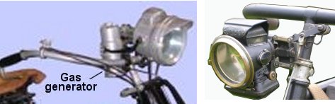
in 1898 headlights became a legal requirement, the law said they had to be bright but their main function was intended as a warning to others rather than illumination for the driver of the car. Oil lamps were used but the preferred option was soon the acetylene lamp. This had a water tank mounted above a sealed container, calcium carbide granules were put into the base of the unit and water allowed to drip down onto it. This produced the acetylene gas which was carried by a rubber hose (the black pipe visible in the photo below left) to the lamp itself. The example shown below left is from the front of a motorcycle built in 1916, the example on the right is a removable type used on a bicycle of similar vintage.
Acetylene headlight
By the 1920s electric lighting was commonplace, by the mid 1930s even horse drawn vehicles often had battery operated lights. In Britain the firm of Lucas dominated motor vehicle lighting, supplying lights for virtually all makes of British car. The firms owner was known as 'The Lord of Darkness' but this was not really fair as the entire electrical system of the vehicle has always been constructed for ease of assembly on the production line rather than reliability in the field. The usual problem with car electrics is the multi-pin plugs and sockets used to connect sections of the loom together so replacing the loom with a bus-system eliminates most of the problems. This however requires a skilled person to do the work and as with all mass produced goods quality tends to be less of a consideration than cost.
The early electric lights tended to be cylindrical, the glass window at the front was made in a similar way to a ships port hole, a glass disc held in place by a metal ring. The ring had brackets designed into it through which ran threaded metal bars (these ran to the rear of the light fitting), butterfly nuts were used to pull the ring back hard against the cylindrical housing to allow the front to be tightened up against a gasket to keep the water out. This evolved into a brass cone shape with a thread on the open end to which the ring securing the glass could be screwed. A separate reflective glass interior fitting was used that also carried the lamp. By the later 1920s this design was effectively the standard on all British vehicles. The front of the cone was protected by a circular glass plate held in place by a simple rim, the rims were sometimes 'chromed' (I think it was a nickel coating then) for the more up market private motor car market but for commercial vehicles a hard wearing enamel coating was used on both cone and rim. By the 1940s the separate glass interior was replaced by a silvered metal reflector assembly, into which the light was mounted, by the 1950s it was standard practice to design the lights into the wings (the bit above the wheels), although the fittings remained standard circular types. From the later 1950s, following the trends in the American market, a chromed rim holding the front glass in place was increasingly common even on low cost private motor cars. By the 1960s the positioning of the headlights was a part of the overall design of the front end of the vehicle, but the lights remained circular and used a removable screw-in bulb.
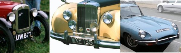
Typical headlights from the 1930s, 1950s and 1960s
The lights on the E-Type Jaguar mark a transition in design brought about by the Americans. After the Second World War the American economy had prospered and with the rest of the world in ruins the American market became a vital component in many industries, including the British motor car industry. In (I think) the early 1960s the American car firms persuaded the US government to pass legislation requiring cars to have 'sealed beam headlights' and banned the use of a glass cover. The original E-Type had glass fairings following the line of the body (as did the Morris 8), these had to be redesinged to eliminate the glass cover, resulting in on-going problems with water collecting and promoting rust.
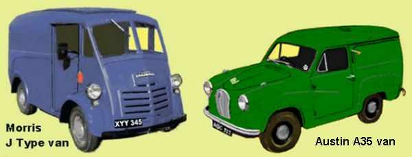
Returning to the circular types Lucas produced a standard range of sizes, the largest I believe were the nine inch diameter type, used on the more sporty machines and on large expensive cars. These were occasionally used on heavy lorries, the braking characteristics of which required a fair view ahead. Seven inch diameter cones were widely used on both motor cars and lorries and this became the standard size for British cars in the post war era when headlights became a built in part of the front wings. Commercial vehicles have traditionally lagged behind private motor cars in many areas and many vans made do with five inch diameter lights (up to the 1950s quite a few vans had only a single headlamp). The sketch shows the older separate light fitting on the left with the built-in type on the right, both these vehicles were popular in the 1950s.
Vans showing external and wing-mounted headlights
Dipped headlights came in in 1937 but it was several years before they became a legal requirement.
The 'sealed beam unit' appeared in the 1960s, in response I believe to changes in American legislation mentioned above, but the early examples were a direct replacement for the standard seven inch circular Lucas fitting which was pretty much standard on all British cars. By the mid 1960s rectangular sealed beam units were being designed into the car as part of its body styling. This may be a problem in the future when owners of 'classic vintage 1970s cars' can no longer obtain the lighting units, however given the flimsy nature of motor car construction in the 1970s and 1980s (where 'accountancy lead' design was very much a matter of 'down to a cost' rather than 'up to a standard')it is unlikely that many such vehicles will survive long enough to become collectable.
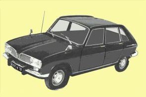
Late 1960s Renault with rectangular headlight units
At the rear of the car the 1898 law required two red reflectors. Several cars were built with rear red lights during the 1920s, mainly at the upper end of the market, but I believe red rear lights became standard in the early 1930s. I believe it was in the 1930s that a law was introduced requiring the number plate to have a light fitted. The example shown below is a Morris 8 E series car from the mid 1930s, this has reflectors on the rear wings and lights on the rear numberplate which have red lenses showing to the rear.
Rear reflectors and lights
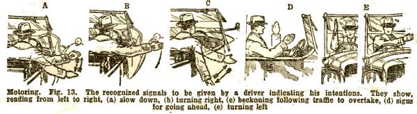
Motor cars did not use illuminated turning indicators until (I think) the 1940s, relying on hand signals made by the driver. The illustration below is taken from an article on motoring published in about 1935. The indication for turning left was later changed to extending an arm from the drivers side window and rotating the hand in a circular motion in an anticlockwise direction (to distinguish it from 'please pass' or 'slowing down' signals).
1930s hand signals
In 1960 the MOT test was introduced (for cars over ten years old), brake stop lamps were made compulsory in the UK and all new cars had to have flashing turn indicators. This latter rule brought an end to the flip-out 'trafficator', a small illuminated orange arm mounted in the door pillar. As there were usually wires feeding the lamp in the flip out arm they were re-used for the flashers and a common type was a flattened hemispherical lamp mounted on the roof beside the central door pillar. I believe these had been introduced in the later 1950s, by which time some new cars (such as the Ford Anglia) had flashing indicators designed into the front and rear of the vehicle. The rules did not initially specify the colour of turning indicators and at least one make had red lenses on the rear indicator lights. The rules only required the indicators to work as intended by the manufacturer, leading to many an argument with the MOT inspectors of the time.
Odds and Ends
Spark plugs were invented by a chap called Edmond Berger in 1839 however his plugs were experimental and he did not patent the idea. There were various alternative methods tried, the rotating 'flame tube' (essentially a wick), 'Hot Tube ignition', 'Wipe Spark ignition', and a 'Low Tension Ignitor', non of which proved entirely successful. Some years later Sir Oliver Lodge perfected the spark plug idea and is generally credited with producing the first viable design (a big part of the problem was developing a mechanism to produce the required high voltage, Lodge produced the first viable coil system (similar to those used today)but he was still developing these in 1909).
The French dominated the spark plug market but the quality was still rather poor. A French cyclist called Albert Champion moved to America where he started making his own spark plugs and selling them to friends. He set up the Champion Ignition Company in about 1904 and did well, so well that the investors took the company away from him but he then set up a new company called AC Spark Plug Company in 1908. Both Champion and AC spark plugs were widely used in Britain, alongside Lodge Brothers &Co plugs (produced by a company set up by two of Sir Oliver's sons). AC spark plugs were actually used to fire the engines on the second and third stages of the rocket in the 1969 moon landing.
The carburetor was invented in 1888 by a chap called Butler, prior to this petrol engines used a small covered pan into which the fuel was pumped, the engine then drawing in the vapour and air mixture from above the liquid. The carburetor was a major advance and remained the standard way to supply fuel to the cylinders until fuel injection was developed. In 1923 Audi introduced the air filter as used on modern cars. The first electronic fuel injection system for cars was invented in 1966 in Britain. In 1970, German firm Bosch developed the fuel injector for production use, then in the 1980s they further developed it into Motronic electronic engine management system, which integrated fuel supply and ignition control.
In 1903 the first windscreens appeared on motor cars (using deadly plate glass), number plates appeared on road vehicles and the speed limit was raised to 20 mph. In 1906 the rear view mirror was invented but it remained a rarity on road vehicles for many years.
Safety glass had been invented in France by a chemist called Benidictus in 1909 but it was only marketed commercially in the 1920's (by a British firm called Triplex based in London). Triplex consists of two sheets of glass bonded to a core of plastic film which holds the glass shards when it breaks. Early safety glass used cellulose nitrate film which went yellow with exposure to light, in 1929 cellulose acetate was discovered which did not have this drawback. Triplex safety glass was put on the British market in the mid 1920's, but this was an optional extra. In 1927 Henry Ford was himself injured in a motoring accident and whilst in hospital he received a telegram from 'Triplex London' expressing the hope that he had not been seriously injured by broken glass and suggesting he should fit Triplex to his cars to make them safer. Ford was impressed, he travelled to London to visit the firm and later paid them to set up a production plant in New Jersey to supply his company with Triplex windscreens. In 1937 safety glass for windscreens became compulsory in the UK (the same raft of legislation made speedometers compulsory).
Mary Anderson of Alabama invented the Windscreen Wiper in 1906, the same basic design is used today. The original device was not powered and hand operated windscreen wipers remained legal into the early 70s. The last car I know of to have unpowered wipers was the Landrover 2A of about 1969 (the motor was an optional extra). In 1921 a British inventor devised a motorised windscreen wiper which used a vacuum pump driven by the engine which remained in common use into the 1960's. It had the unfortunate characteristic of slowing down when you speeded up and speeding up as the engine slowed down. The main weak point was a small diaphragm in the motor and if this failed you had to hold your thumb over the orifice to allow the vacuum to build up, when you removed your digit the wiper thrashed back and forth frantically for a second or so then slowed to a stop, at which point you put your finger back over the hole. The problems of the windscreen wiper coupled with higher speeds and cable operated brakes with a tendency to pull the car off to one side made driving in rain rather more exciting than most people would have liked.
In 1849 Volvo produced the first car equipped with seat belts but they remained very rare until the later 1950s when they began to appear on the more 'sporty' vehicles. In 1950 a car by Nash became the first American production car to be fitted with seat belts, only initially on the passenger seat and intended to prevent a sleeping passenger sliding off the seat during braking. Volvo introduced the most common modern three-point seat belt (which has a belt across the lap with another across the chest), developed by Swedish inventor Nils Bohlin, in 1959. This device was not patented as the inventor and Volvo felt it was too important to be restricted. Sports car owners favoured an aircraft style belt with two shoulder straps extending down to a central buckle on the lap belt and there was some debate about whether the three point or four point design was the best, the three point proved as effective and as it was easier to fit and use it won the day. Seat belts became a legal requirement for all new cars from 1967 but wearing them only became a requirement in 1983 and then for front seat passengers only.
Up to the 1960s the interior layout of the vehicles and the materials used meant that even a fairly minor crash often involved a fatality or two amongst the occupants, but this was accepted as part of the 'adventure' of motoring. Up to this time any motorist had to be somewhat intrepid, able to repair a breakdown by the side of the road and familiar with the workings of the machine. Over the next twenty years however new technology, notably digital control of sub systems transformed the motor car into an altogether different machine, closer to a living room on wheels than the cockpit of a biplane. It has been estimated that approximately 30 million people have died world-wide in motor car road accidents between the 1890s and the year 2000, the world-wide death toll is estimated to be running at approximately 900,000 per year in 2005 (Source: Global Road Safety Partnership), so work remains to be done. In the longer term fully automated vehicles should solve many of the problems, although there is currently a strong negative reaction from motoring enthusiasts (they also objected to speed limits and seat belts).
British Racing Green
The first international motor car race, known as the Grand Prix (big prize) was organised in 1903 by an American newspaper proprietor called Gordon Bennet. The plan was to stage the race in Britain, however as there were no race tracks normal roads would need to be used and the British had a speed limit of 12mph. The solution adopted was to hold the race in Ireland (then a part of Britain but not subject to the 12mph speed limit). Each country had to choose a colour and the British entrant (a Napier capable of 80mph) used green as a mark of respect to the Irish. The French adopted blue, Italy black, Belgium yellow, the Americans chose red and the Germans went for white.
For many years motor racing was conducted in national colours, although the Germans switched to silver (the Japanese taking white), Italy adopted red (I am not sure what colour the Americans then adopted). The actual shade of green used on British cars was not closely specified, the Bentleys of the 1930s used a rich dark green built up from several layers of paint and varnish called Brunswick Green (a hard wearing colour that had found favour with the railway companies in the 19th century) that could trace its origins to the 'camouflage' uniform of the British sharpshooters. The same colour was then adopted by Aston Martin, Cooper, Lotus, Sunbeam and Jaguar.
Things changed again in 1968 when Colin Chapman's Lotus 49 won the world championships wearing the sponsors colours (Gold Leaf cigarettes, red upper and white lower with gold pin-striping). Since then the majority of racing cars in the professional sport have been painted in sponsors colours.