See also the Lineside Industries section on 'Canals, docks, harbours and ship types' for more information on ship types and port facilities. See Appendix One - Fishing boats and ports for more on the development of British fishing fleets and associated ports.
Rivers & Canals
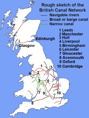
Away from the coasts the small ships and coasting craft could make their way inland by following the rivers. Britain has several navigable rivers, most of which form small groups leading to a common estuary. There is a network of rivers feeding into the Humber, notably the Trent, and farther south are the Witham, Nene and Ouse. The Thames and its tributaries serve the South East, the Severn and Avon in the South West and the North West has the Mersey, Irwell, Weaver and the Dee. Between 1620 and 1760 many of the rivers were improved by 'Navigation' companies who were then authorised to charge tolls for craft using the waterways.
Fig ___ Rough map of the British inland waterways
Small coastal sailing ships and ships trading to the continent could make their way a long way inland on the rivers. At the beginning of the nineteenth century even the ships engaged on long sea passages to India and the Americas could make their way up the Severn to Gloucester, the Thames to London, the Dee to Chester and up the Mersey to Liverpool and Birkenhead.
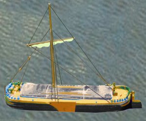
Fig ___ Model of a bluff fronted Humber or Yorkshire Keel
There were a number of sail powered craft employed on the rivers each area having its preferred type, one common feature was the very tall mast, required when sailing inland. In the North East there were the Humber or Yorkshire 'Keel' and the Sheffield cargo sailing barge (typically sixty one feet (18.6m) long by fifteen feet (4.5m) wide) farther south in East Anglian there was the Norfolk Wherry which was typically fifty feet (15m) long by fifteen feet (5m) wide.
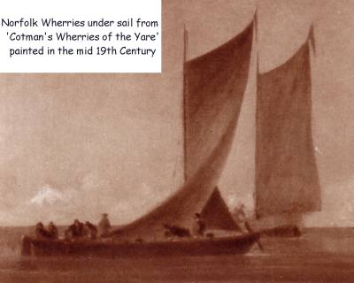
Fig ___ Painting of a Wherry under sail
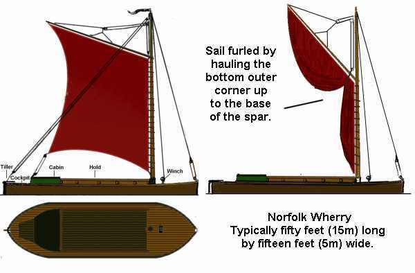
The sketch shows a Wherry in full sail and also how the sail was furled when at anchor or moored alongside for loading or discharging cargo. The wherry could lower its mast to pass under bridges.
Fig ___ Norfolk Wherry
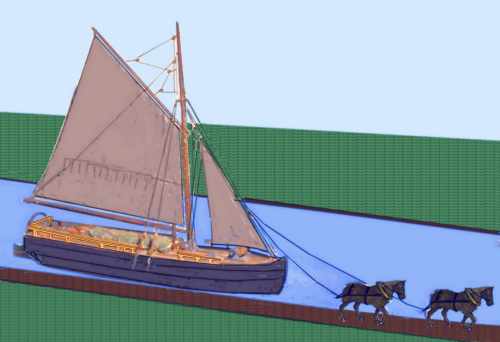
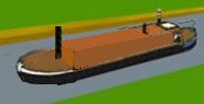
The Thames of course had its famous sailing barges whilst in the North West the principal craft was the Mersey Flat (illustrated below), which was between sixty feet ( ) and seventy feet (21.3m) long by about fifteen feet (4m) to seventeen feet ( ) wide. These were also used on the river Irwel and river Weaver.
Fig ___ Mersey Flat
The sketch shows a Mersey flat with a low rail at the sides, indicating that this was the sea-going variant able to make (very short) coastal hops. There was also an inland only type with no rails, both types were also seen with two masts, the second being smaller and set about a quarter of the way in from the stern. The barge is shown being assisted by two horses, these had to be stabled at intervals along the canals and inland waterways. Crossbred Shires were the most common type used, typically about five feet high at the shoulder. The last horse power used on British waterways was in about 1953.
In the 1890s a steam engine was added to the Weaver variant, although the steamers were larger at about 90 feet long by 21 feet wide and able to carry 250 tons of cargo. These steam flats continued in use into the 1960s, mainly carrying salt. The logical development was the motor flat, an example of which is shown below. These remained in service into the 1970s at least (possibly longer).
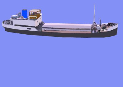
Fig ___ Riverine motor craft
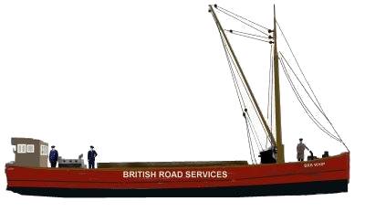
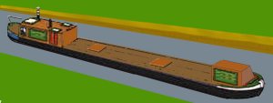
The motor powered barge was used on most of the larger rivers, notably the Mersey, Severn and Thames (probably others as well) and they remained in widespread use into the 1960s, with some soldiering on into the 1970s. The example below was called 'Whip' and operated in the Severn Estuary and along the South Wales coast, it is unusual in that it was owned by British Road Services, not the British Waterways Board, although I have no idea how this came about.
Fig ___ Coastal or river motor barge
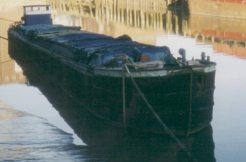
The example shown below was photographed in Hull docks in 2004 by Stan Pavey, this is a typical modern broad beam barge
of a type seen since the later 1930s.
Fig ___ Motor barge in Hull docks
The Leeds and Liverpool Canal is different in that it was designed for what are known as 'short boats' 60ft (18m) long by 13 feet wide, slightly smaller than the sea going 'flats' and 'trows' used on other broad canals.
The broad beamed barges proved less popular in the South West where the existing fleet of sea-going schooners and ketches continued to operate into the rivers up to about the 1950's. There were however a number of Severn 'Trows' and Tamar Barges, an example of the latter in restored condition is to be seen at Cotehele Quay on the Cornish bank of the Tamar in Cornwall (this restored quay is unfortunately not rail connected). These sea going vessels were more ship-like than the sailing barges used in the South East.
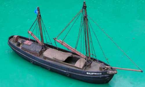
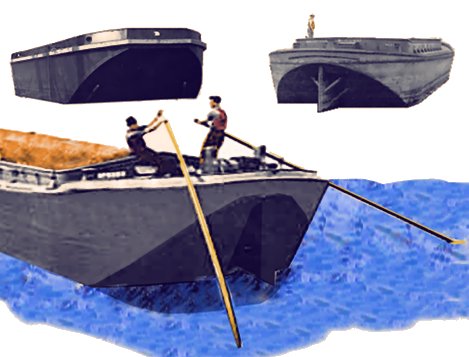
My model has the sails furled to the boom at the base of the mast. In practice the sails were often removed completely, leaving bare poles, but most people seem to find the presence of sails pleasing. On my model the boom is swung out slightly to clear the hold but on the prototype it was common practice to rig either the main (lower) boom or the smaller (upper) boom over the hold with a block and tackle for loading or unloading the cargo. Also there would normally be a rowing boat tied upside-down on top of the hatch cover, on my model this has been lifted off into the water (not shown in the photograph).
Fig ___ West Country sailing barge
This is a boat for a model railway not a model boat so the detail has been kept
to what I consider an acceptable minimum, and the height of the mast has been reduced by removing the usual upper section due to a bridge down stream' (this is prototypical, the ships with this feature were known as 'stumpies'). The model is loosely based on a photograph in The Railways of Somerset' by Colin Maggs (ISBN 0750902264) of the Lilly! owned by the Weston Clevedon &Appledore Light Railway. The Last Days of the Sailing Coasters! by Edmund Edlington (ISBN 0112903363) contains the memoirs of the captain of this ship but very little on the railway connection. The model is 14.5cm from front to back, corresponding to a vessel about 20 meters or 67 feet long, with a cargo capacity of a hundred tons or so. Sailing barges of this type would usually be used for bulk cargo such as coal, stone, timber, grain or manure. Mine has a regular run taking broken stone (delivered in three plank wagons) to Northern Spain for a building job, back loading with onions (collected by ventilated vans).
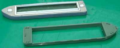
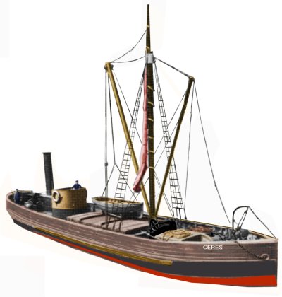
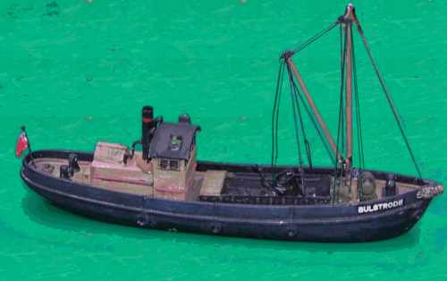
The model shown was produced from the former Ertl 'Thomas the Tank Engine' barge Bulstrode, modelling this vessel was described in detail in Railway Modeller magazine June 2000.
The same model serves well as the basis for a sailing barge,for example the Mersey and Irwell 'Flat' coastal barge shown in the sketch above.
There were of course difficulties with rivers, going up-stream craft had to battle against the flow, close to the coasts they were tidal and shifting sand banks and silting up of the berths was a continual problem. The River Dee had seen Chester develop as one of the most important Roman ports but silting up left the wharves and berths isolated inland. Also the rivers were not interconnected so goods often had to be hauled overland or taken round the coast and here there were the usual problems associated with the British weather and the often dangerous British coasts. In one example quoted in a canal prospectus from about the 1780's two boats left Newcastle on the same day, one heading for Bombay in India via South Africa, the other bound for Liverpool via the North of Scotland, the first to arrive was the ship going to Bombay.
The canal, a completely artificial water way, was not a new idea, the ancient Egyptians constructed a navigation canal around a waterfall on the Nile River more than 4,000 years ago and the Babylonians built a few at about the same time. The Chinese spent seven hundred years building their own Grand Canal, only completing it in the 1200's and during the 900's, the Chinese built the first known canal locks.
Important early European canal systems were built in the 1100's and 1200's in the region that includes present-day Belgium and the Netherlands. The Canal du Midi, completed in 1681, became an important waterway in France allowing the small ships of the time to travel from the Mediterranean Sea at Sete to the Bay of Biscay by way of Toulouse and the Garonne River.
The Romans built a few canals in Britain, notably the Fossedyke running between the River Trent and Lincoln but, following the Middle Ages, although French and Italian canal systems were being successfully developed the British concentrated on improving the rivers.
Canals have several advantages over rivers, they could be built where they were needed, reducing the requirement for horse drawn tramways bringing minerals from the mines to the rivers. They had no currents to deal with and horse drawn barges travelled faster than road carts, with average speeds in the 2-3 miles per hour (3-5 kph) range. Only freezing winters or very serious droughts had any serious effect on canal use whereas on land even moderately bad weather could make the roads impassible.
Sailing barges built for the rivers were quite large, carrying anything from sixty to a hundred tons but on a canal, with no currents to contend with they could be pulled along by a single horse if the winds were unfavourable. As a comparison a single horse could carry about an eighth of a ton and a one-horse waggon could carry about half a ton, assuming the roads were passable.
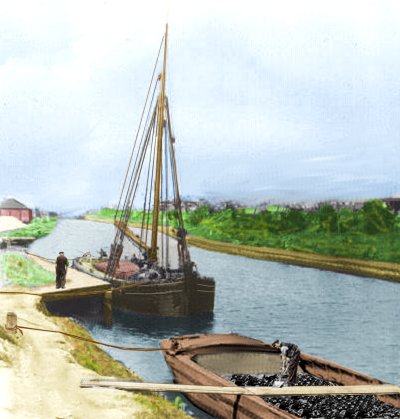
Fig ___ Typical scene on a canal about 1900
As they required the legal power to take water, purchase land and what have you an Act of Parliament was required to authorise the building of a canal. The Act stipulated the money which could be raised from shareholders, the route the canal would take and even the charges and tolls that could be levied by the canal company, usually quoted in pence per ton-mile.
The first canal authorised by Parliament was started in 1755, following rioting in Liverpool over the price of coal. The plan was to improve a small river called the Sankey Brook to take barges and a Mr. Berry, the Liverpool Docks engineer, was hired to do the work. Mr. Berry looked at the job and decided to build a completely artificial canal instead and although technically illegal no one seems to have complained when this canal, subsequently called the St. Helens Canal, opened in 1757.
The canal was built with only the experience of the river navigation's to draw upon. Wooden swing bridges allowed sail powered craft to use the canal and where sails could not be used gangs of men pulled the boats as they did on the rivers. Within a few years however it was realised that a single horse could pull a substantial load along the canal and quite rapidly the horse became the standard motive power. These had to be stabled at intervals along the canals and inland waterways. Crossbred Shires were the most common type used, typically about five feet high at the shoulder. The last horse power used on British waterways was in about 1953.
The next major work was entirely financed by Francis Egerton the Third Duke of Bridgwater who wanted to carry coal from his mines at Worsely to Manchester, a distance of over ten miles (16 km). The nearby Sankey Brook canal was benefiting his competitors and the Duke's first plan was for a short canal from his mines down to the River Irwell but the Irwell Navigation Company felt they could dictate terms and quoted very high rates. The Duke decided to build a canal right into the heart of Manchester, by-passing the Irwell completely. There was a lot of opposition, notably from the Irwell Navigation Company, but in 1759 the Duke got his act of parliament. He hired a semi-literate former millwright by the name of Brindley as the chief engineer for the project.
At the Duke of Bridgewater's mines passages which had been dug to allow water to drain away were widened to allow the boats direct access to the mine workings. The boats used were known as 'starvationers' and were simple in the extreme, small enough to pass inside the mine tunnels they were little more than hulls. The price of coal in Manchester fell by half when the canal opened and the cost of fresh vegetables fell by as much as two thirds. The Bridgwater Canal is often quoted as the first British canal, mainly because it was the first which did not follow an existing water-way, it even bridged the River Irwell with an aqueduct.
Coal from Worsely was also subsequently carried in rectangular wooden containers, each carrying about six tons, which were carried to the canal side on narrow gauge railway trucks and lifted into the barges by a crane. At the Manchester end the canal ran into a tunnel under Castle Hill and the containers were hauled up a vertical shaft by a water-wheel powered hoist. When the Liverpool and Manchester Railway started operation in the 1830s the containers were a regular cargo, transported in pairs on simple open wagons called 'skeliton waggons' (sic).
The Bridgwater Canal was the first and last British canal to be entirely financed by one man, building it nearly bankrupted the Duke but the subsequent profits were a significant factor in the popularity of canals in Britain. It was subsequently extended out via Warrington to the Mersey at Runcorn near Liverpool and although the mines at Worsely closed in the late 1880's the Bridgwater canal continued in commercial use into the 1970's.
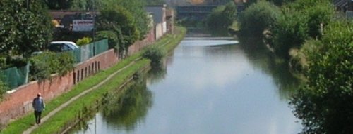
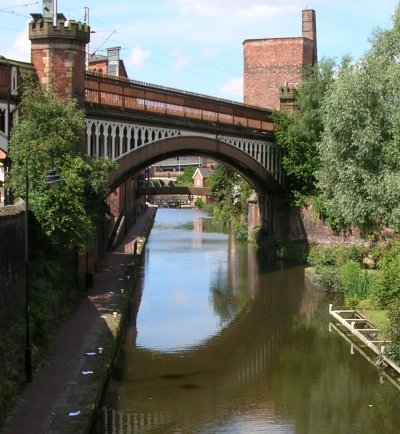
Fig ___ Bridgewater canal approaching Broadheath
To avoid monopolies the government decreed that the canal and river 'Navigation' companies would function in the manner of toll roads, providing waterways for contractors and privately owned craft, they were not to operate craft themselves. This meant that the small operator could compete on equal footing with the larger concerns such as Pickfords (an old established firm who began using canals in the 1790's). This rule was scrapped in 1849 and the canal owners subsequently built up quite large fleets of their own craft but the independent operators continued to operate and several substantial firms were built up over the years.
When Wedgwood began using Cornish clay in his potteries it was carried by sea to the River Weaver and hauled from the river to the works by pack horse. This was expensive and inefficient and Wedgwood was one of the promoters of the Trent & Mersey canal which opened in 1777. This was one of the first trans-pennine canals and Wedgwood built his new works and his new house facing each other across the 'cut'.
By 1830 there were over four thousand miles (6,500 km) of inland waterways in Britain, and most were making a tidy profit. The canal network was mainly centred on the Midlands, branches from the Trent and Mersey canal ran to the Thames at Oxford and the Severn at Stourport. Most major canals joined with navigable rivers, the Birmingham Canal joined the Shropshire canal system, giving access to the rivers Dee and Mersey. Another canal also ran from Birmingham to the Severn, this time joining the river at Worcester and the Grand Junction Canal ran all the way from Birmingham to meet the Thames at London with branches to Leicester and the River Soar. In the south of the country the Kennet & Avon Canal connected the river Severn via its tributary the Avon to the Thames via its tributary the Kennet. The Aire & Calder Canal, really more of an improved river, was probably the busiest canal in the country. It runs from Hull to Goole and was mainly noted for carrying coal.
Unlike the Europeans the British left the building and operation of canals entirely in private hands, so where the French built a network of canals geared to take 300 ton barges in the late eighteenth century and the Germans followed in similar vein, the British made do with their network of incompatible systems. Just prior to the First World War there was talk of a government funded improvement to the great cross of canals from Hull to Bristol and from London to Liverpool which would allow 100 ton barges direct through passage. The railways opposed this idea and there was doubt regarding supplying enough water for the scheme (although the French and Germans had managed). In the end the idea was dropped and there was then no real investment in the inland waterways until the 1970's.
In the days before the railways the canals were the highways of the country, carrying all forms of manufactured goods as well as raw materials. The railways provided stiff competition but river and canal craft were well suited to carrying materials in bulk, the most important cargo was coal but a lot of limestone was shipped to iron works. Other bulk loads commonly carried by canals included grain (loaded at the canal side closest to the fields), 'hammerscale' (the floor sweepings from iron works), coke, building materials, gravel, sand, cement and even horse manure.
Generally, for bulk trades, such as coal to power stations and the like, inland canals remained cheaper than railways (and a lot cheaper than roads) right up to the end of their commercial operation. The British Waterways Board published figures in the early 1970's which suggested that for a given cost a single ton of freight could be moved about four miles (6.4 km) by air, sixty miles (97 km) by road, two hundred miles (320 km) by rail and over four hundred miles (650 km) by water.
In the post war economy, with the development of efficient road vehicles and improvements to the roads themselves in an era of cheap oil, coupled with a cultural fondness for all things 'new' told heavily against the waterways. The narrow boats generally ceased trading in the early 1960's, although some regular traffic was still shipped on long hauls by narrow boat into the early 1970's.
One specialist long haul was the carriage of casks of imported lime pulp to the Roses works at Boxmoor in Hereford via the Grand Union Canal. This traffic continued into the early 1980's and was probably the last significant commercial use of narrow canal boats.
The gated 'pound lock' familiar to modern canal users was an Italian invention, introduced to Britain as early as about 1566 on the Exeter Canal, which was a short cutting dug to by-pass several curves on the River Exe.
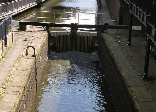
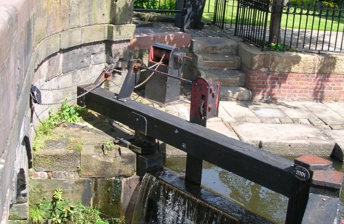
Fig ___ Lock on the Rochdale Canal
If there was insufficient space for the lock gate arms to swing, as sometimes happened where the lock was connecting a new canal to an existing waterway close by a bridge, then a mechanical aid in the form of a simple windlas was added as shown below
Fig ___ Lock gates in confined space
There are a few points to note about locks, firstly the gates of the lock must close to form a V facing the higher side of the lock, in this way the water pressure helped to reinforce the seal. I have seen one model layout where the gates were installed facing the wrong way. Secondly on many of the smaller locks two gates were provided at the down-stream end, these gates opened into the lock itself and by using a pair the room required was kept to a minimum, at the upper end of the lock the gates opened outwards and on many locks on the narrow canals only a single large gate was provided at this end.
Fig ___ Lock on an early 'broad' canal
To negotiate the hills which characterise the industrial areas of Northern Britain flights of locks were required, which used a lot of water and slowed traffic down. In the illustration above showing a lock on a broad canal the two locks have a basin or 'pound' between them to allow craft to pass each other in the middle, on some of the narrow canals there were entire flights of locks with no basins, a series of barges would pass up through the locks, the water emptied from the first filling the lock for the craft following behind and so on. This used a lot less water.
The only practical alternative to the lock is the 'lift', this consists of a steel trough which is lowered into the water. The barge enters the trough, the ends of the trough are closed and the entire structure is then lifted or lowered to the connecting canal. As the boat displaces its own weight of water the weight of the trough does not change and two troughs can be set up with the weight of one ballancing the weight of the other. This meant that a very small motor could provide all the required power. There is a working example in Cheshire, where the Anderton Boat Lift has now been restored and earns its living moving holiday craft.
One big problem faced by the inland waterways was than canal designs and river improvements were not harmonised. Brindley built his locks on the Bridgwater canal about seventy two feet (22m) long by fifteen feet (4.5m) wide to carry the local Mersey Flats whilst in the North East canals and locks were built to carry the Yorkshire Keels and similar craft which were fourteen to sixteen feet (4-5m) wide. Canals of this type are called 'broad canals' and the craft which worked on them are technically 'barges' (that is they were all more than eleven feet (3.3m) wide).
Fig ___ Bridgewater broad canal running into central Manchester
Brindley was hired to build several canals in the middle of the country, notably the canal feeding Mr Wedgewood's factories, and to save water he decided to build the locks only seven feet two inches (2.1m) wide, half the size of those on the Bridgwater and requiring only a quarter of the earth works to build. Obviously the existing barges and coastal craft could not negotiate these narrow locks and a new craft, the 'narrow boat' was introduced, seventy feet (21.3m) long but only seven feet (2.1m) wide. The problem with the narrow boats was that although their thirty ton payload seemed sufficient in the eighteenth century it was too small to compete with the railways in the nineteenth. The network of narrow canals in the Midlands centered on Birmingham, a city that ended up with more canals than Venice.
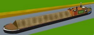
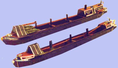
For modelling purposes you can get away with a common 'narrow boat' just about anywhere as these were designed for the smallest locks in the country and could therefore travel on any of the inland waterways. The narrow boats usually had a small cabin at the rear for the operator or owner, the main part of the boat was a large hold, covered if required with canvass which could be suspended from a wooden plank running along the centre and supported on square wooden posts.
Fig ___ Narrow boat
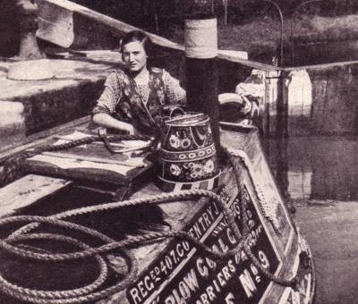
In the later half of the nineteenth century competition, mainly from the railways, forced boatmen to live on board with their family. The small cabin at the back of the boat was about nine feet by seven feet and the whole family often lived in this space. On some boats a small cabin was added at the front for the children, but this used up valuable cargo space and was not very common (although standard on the tar and oil carrying barges operated by Thos Clayton). The bargees as they were called took great care of their boats, keeping them clean and tidy even whan carrying cargo such as coal. The example shown is a coal barge that has just entered the lock, note the ornate painting on the water bucket on the cabin roof (very difficult to replicate in N but a wrapper printed on a computer can be used).
Fig ___ Narrow boat entering a lock in the 1930s
Small 'tub boats' were introduced on the Aire & Calder Navigation in the nineteenth century. These are simple floating boxes, the originals were square and carried about fifteen tons of coal (which was equivalent to one and a half railway wagons). These boxes, called Tom Puddings on the Aire & Calder, were towed along in strings of up to twenty at a time with a special floating 'bow' section attached to the front of the chain. Similar craft were soon seen on other canals such as the Shropshire Tub Boat Canal and the Bude Canal in Cornwall, one common use being ferrying coal to gas works. On the Aire & Calder Canal they carried coal to Goole where they were lifted by a large hoist and emptied into the holds of coastal ships. Over the years there were various designs built, each larger than the last, and they continued in use into the 1980's at least (possibly later) supplying the Ferrybridge power station and I believe the hoist at Goole docks feeding the coasters ceased operating in the early 1990s. The tugs used were originally steam, these were replaced by diesel tugs in 1979,
Another unusual design of boat was found in South Wales, these were a simple open design with a prow at both ends and no cabin as such, resembling the original 'stavationers' of the Bridgwater canal they were about sixty feet (18.3m) long and about nine feet (2.7m) wide.
Steam power was tried on the Sankey Canal in 1793 but developments were hampered by Watt's patents and steam did not become common until small and efficient engines were developed in the late nineteenth century. Adding a steam engine cost the boat about ten tons of cargo and of course fuel had to be paid for so even then horses remained the norm. The one advantage of the steam powered narrow boats however was that they could pull two unpowered 'butty boats' behind them.
Fig ___ Steam narrow boat and unpowered butty
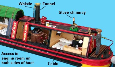
Note that on models of canal barges a chimney does not signify an engine, from the turn of the century railway competition meant that more 'bargees' lived on their boats and the stove required a chimney of some form. Steam powered barges generally had the engine mounted forward of the cabin with its own funnel as shown above. The cut-away shown below is from a photo taken at the Astle Park steam and vintage vehicle event, this was being sold (I believe) as a 'dolls house' (some detail has been removed to make the illustration more clear).
Fig ___ Cut-away of a steam narrow boat showing engine room
Steam powered 'tugs' were built to tow barges through tunnels and they were used on several of the broad canals and in some harbours simply to tow barges about. As an example based on photographs some of those used in the Manchester Docks and along the Bridgwater canal (a broad canal) were about sixty feet (18m) long by ten feet (3m) wide. The sketch below is based on a photo taken in the 1930s showing the tug with a typical broad canal dumb (unpowered) barge alongside a quay.
Fig ___ Manchester Ship Canal Steam Tug and Barge
Most steam tugs on the narrow canals resembled short narrow boats with a 'cabin' extending their full length and a chimney typically about a third of the way from one end.
Fig ___ Narrow Canal Steam Tug
Horse towing of barges although increasingly rare was still seen into the mid 1950's and steam powered Weaver Flats were still trading (principally in the salt and chemical trades) into the 1960's but most craft used compact and efficient diesel engines from about the 1920's. These could also tow a couple of 'butty boats' but often only had one in tow as many locks could only take a pair of boats in one lift. Langley offer a set of motor boat (diesel engined) and towed 'butty' boat in their cast metal range.
For intensive short-haul operations 'day boats' with no living accommodation continued to be used right up to the end of canal working in the 1960's and 70's. By the 1960s boats were typically built using a steel hull, this was the norm for larger 'lighters' used in the ports, but in the 1940s a number of large barges were built of concrete (mainly for use in ports).
The railway companies bought up several canal businesses and made some limited use of them, this line of investment was blocked around the beginning of the twentieth century however and the railways only owned about half the total canal network. The LMS had quite a large fleet of canal boats in its livery and the Great Western Railway used canals to supply their sleeper depot outside London with wood and creosote (carried in tanker barges, discussed below), the finished sleepers being shipped out on railway wagons.
Narrow boats were generally very standardised but up to 1970 Thomas Claytons of Oldbury in the Midlands operated a fleet of narrow tanker barges to carry oils and the various liquids and tar produced at gas works. These had the same basic plan as a narrow boat but they sat very low in the water when loaded and had square hatches on the deck for access to the tanks. There were usually two of these hatches, one about a third of the way back from the front, another close to the after end of the cargo deck.
Fig ___ Narrow boat tanker
River tanker barges remained in use (notably in the North East) into the 1980's. These were often quite large, built to suit the river or canal on which they ran, and they often had a 'trunking' about three feet high by three feet wide running fore and aft along the deck. The loading hatches were fitted on top of this trunking. The cargo was filled until the top was inside the raised trunking so it had only a small surface area and could not tip the boat over as it sloshed from side to side. Rather than trying to modify a kit it would probably be easier to build a model of a tanker barge, narrow or broad, from scratch.
In 1972 a new system was introduced called BACAT (Barges Aboard Catamaran), this used barges built to continental standards and capable of carrying 140 tons (142 tonnes). The idea was to allow Britain to send and receive goods to and from the extensive European network of modern canals and river water ways. The rivers and canals from the East Coast as far inland as Sheffield was improved to take these new barges. At the coast the BACAT ship could load ten of the barges, lifting them out of the water and securing them on its deck. In addition the BACAT ship could also take three American 'LASH' (Lighter Aboard Ship) barges, these carry up to 350 tons apiece, on BACAT they remained in the water and were secured between the catamaran hulls of the ship. The Americans were at the time pushing LASH as an alternative to ISO containers, the American LASH ships lifted the barges on board but they only paused briefly off-shore to load or deposit barges before continuing on their way. The barges could then be taken inland and loaded or unloaded at leisure.
The BACAT scheme failed because of the dock workers union which insisted that their men be used to load and unload the barges, even where a firm had its own wharf inside its factory or depot. The dock workers in all ports threatened strike action and in 1974 the BACAT scheme was abandoned and the two ships were eventually sold to a Far Eastern company. A number of the barges were retained however and continued to operate from Sheffield down to the Humber
Port and Harbour Tugs Barges and Lighters
A tug is a lot smaller than a ship but they are associated with larger ports and harbours, which can be an advantage on a model layout. Paddle tugs were in widespread use by the mod 19th century but the screw propeller was dominant by the beginning of the twentieth century, although paddle tugs remained in use into the 1930s. The photo below shows a model paddle tug, points to note are the two lights, one above the other on the foremast (all tugs need these lights) and the arched metal bars running across the after deck so that if the tow line went slack it would not catch on any deck fittings.
Typical paddle tug
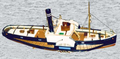
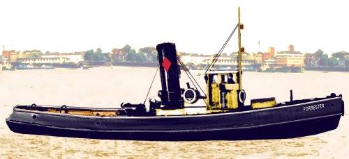
The tow hook on a tug is always somewhere close to the centre of the hull and mounted on a swinging arm so the pull on the hook is always straight to allow the quick-release to operate. The steam tug remained a common sight in British ports into the 1950s, a couple may have survived in to the 1970s. There is a preserved example, the Mayflower built in 1861, at Bristol Industrial Museum & Maritime Heritage Centre, the example shown below is typical of the breed and might have operated in any British port.
Typical British steam tug
Modelling tugs is discussed in more detail in the section on Lineside Industries - Canals, Docks, Harbours and Ship Types
Also seen in many ports would be 'lighters', large unpowered barges that could be taken alongside a ship at anchor to part discharge (or load) a cargo. This saved some time at the quayside and allowed deeply laden ships to 'lighten', reducing their draught so they could reach berths in shallow water. The advantage from a model railway perspective is that ports often had small docks specifically to handle smaller craft such as lighters, allowing one to suggest a larger port without having to model a larger quay.
Lighters were large, usually larger than most barges, some had vertical bows and stern with the rudder sticking out at the back (like a large barge) but a lot had a distinct cut-away at the bow and stern. Although large these could be moved about by a man (or two) working a long oar called a 'sweep'. This was even seen on rivers where one would assume the current would be too strong.
Port or harbour lighters
Barges were also used in the same way, and they are easier to model (at least I find them so). Noch offer a model suitable for OO layouts in their range. For N Gauge layouts the Airfix military 'Pontoon Bridge' set includes five barges which can serve for a 'barge' type lighter, although they are rather deep for use 'as-is' and benefit greatly from being reduced in height by cutting them in half. The centre of the lighter has a low raised coaming on which ship-type curved supports were mounted to carry 'hatch boards', these then being sheeted over with canvass secured by wedges in the coaming. At each end there is usually a rectangular hatch about three feet square, for which a square of 30 thou card will serve in N. The photo shows an Airfix barge being modified in the way described.
Modelling lighters
A specialised class of tanker barge, of particular relevance to railway modelling, is the 'bunker barge', a small vessel used to supply ships with fuel and lubricating oil. Bunker barges range in size from something slightly larger than a canal narrow boat up to substantial ships of similar size to a coastal vessel. A common feature of these barges is a long boom that can be used to lift the end of the hose onto the deck of the ship but this was not always fitted as the ship could haul the hose up using its stores crane, a simple air-winch clamped to the rails or even by manpower with a rope. The fuel is usually supplied in bulk but the lube oil may also be delivered to the ship in drums. It would be perfectly standard practice to have some 'cargo slings' (large nets) containing green painted 45 gallon drums on the deck of such a barge. It is not uncommon for other stores to be delivered to the ship on the same barge, again these would normally be wrapped in a large cargo net ready to be lifted on board by the ship's stores crane. The advantage from a model railway point of view is that no shore installation is required, loading these vessels at a quayside from railway tank wagons would be perfectly acceptable in a smaller port (although where space allows a separate siding would be used to reduce the problems of oil spill contamination and possible fires).
Do beware however, there were other tanker type barges used in ports, Liverpool had Camel No1 and No2, which were used to supply fresh water not oil.
Coastal Shipping
Note - Ships hatches are described in the Lineside Industries section under 'Canals, Docks, Harbours and Ship Types'
Britain is an island and most people live within about eighty miles (130 km) of the sea, however sea transport tends to be slow and there is always the danger of sinking. On the plus side water transport is cheap and energy efficient and even today coastal shipping remains important whilst some of the more developed canals and inland waterways continue to see commercial traffic.
It is difficult to make concrete suggestions for suitable kits which might be pressed into service as coastal sailing craft for an N Gauge layout as the model ship market seems to be rather less stable than most and kits appear and are withdrawn quite frequently. One problem here is the difficulty of finding illustrations of these vessels moored alongside quays. Usually they are shown with all sails set to evoke the romance of sailing.
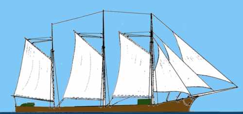
A good all-rounder that might have been seen in any small port is the West Country Schooner, that is a three-masted vessel using fore-and-aft rig on all three masts and usually with a square sail rigged on the upper part of the foremost mast. This kind of sail rig is easier from a modelling point of view than the fully square rigged ship. There is a preserved example, the Kathleen and May, which had the square rigged top sail removed (making the modelling easier). Modelled in British N she would be roughly ten inches long by one and a half inches wide and from the water-line to the top of the middle mast (the highest) would be about five inches. A vessel of this general type can be built using a commercial hull (to provide the complex shape) with home made masts and deck fittings.
Fig ___ West Country Schooner
A ketch is similar but smaller, it has two masts.
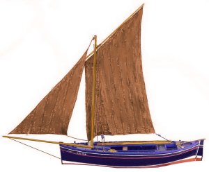
A lugger is a ship or boat with a four cornered sail suspended from a spar which is hauled up the mast. As the spar crosses the mast it has to be lowered so the spar can be 'lugged' round to the other side of the mast to change direction. This sail alows the vessel to steer close to the wond and makes it fast but it is heavy work and was associated mainly with fishing boats which originally had enough crew to manage the sail. With the introduction of small steam winches at the end of the 19th century the lugger enjoyed something of a resurgence as a fishing vessel and was common up to the 1920s.
The example shown below is a typical fishing lugger which would serve for any British port from the arrival of the railways up to about 1930.
Fig ___ Typical small sailing fishing boat with lug sail
For more detailed information on sail designs see also the section on Lineside Industries - Canals, docks, harbours and ship types.
Small coastal sailing vessels continued in use into the 1960's but sailing ships with steam or diesel 'auxilliary' engines were built from the later part of the nineteenth century and all-motor (or steam) ships were increasingly dominating the scene from the 1920s on.
Small steam powered coastal vessel appeared in about 1860 and up to about 1890 these were generally rather stubby craft with a simple box like superstructure surmounted by a cylindrical funnel at the rear and the steering position located in the open behind that. Typical dimensions were about seventy feet (21.3m) long by twenty feet (6m) wide. These small vessels often seem rather short and wide, in part this was a limitation caused by the locks on many navigable rivers, for example the Crinian Canal in Scotland could accommodate vessels up to 88 feet (26m) in length (near enough 7 inches or 18cm in British N). This set the standard size for the small steam coasters or 'Clyde Puffers' operating out of Glasgow, a type which remained in service into the 1960s.
The photo below was taken at a stand run by the Manchester Model Boat Club at a steam rally in about 2002, it shows a typical 'Clyde Puffer' type vessel, a type common as the name suggests on the Scottish coasts. The wheelhouse is enclosed so this example probably dates from no earlier than the 1890s.
Fig ___ Clyde 'Puffer' type steam coaster
The example shown below is a type favoured on the Bristol Channel and dates from the later 1860s, it is a larger type, about eighty tons and perhaps a hundred feet long with an open 'bridge' from which the ship is steered. She carries sails, currently furled against the mast, which would have been used to economise when winds were favourable. The hull is wrought iron but note the prominent wooden rubbing strake along the ships side at the top of the black 'boot topping' paint. The small gallows at the bow is called the 'cat head' and was used to lift the anchor inboard where it was lashed to the deck when at sea.
Fig ___ Small late Victorian steam coaster
By about 1910 coastal craft were getting larger but vessels of about sixty to a hundred feet (30m) length were still common. The steering position had moved to the front of the engine house by this time and was usually mounted on a raised platform (the 'bridge'), after about 1920 this was commonly covered by a 'wheelhouse' with glass windows.
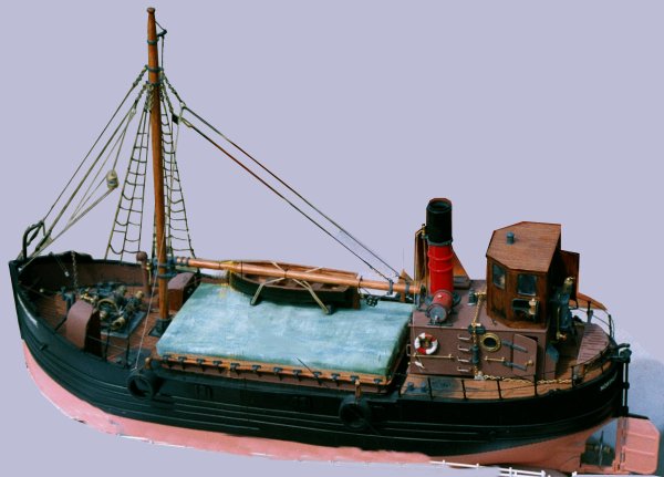
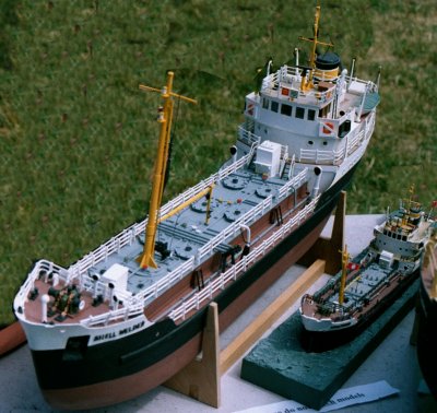
The classic reference work on these small coastal steamers is C. V. Waine's 'Coastal Steamers and Short Sea Traders' which is detailed in the bibliography. The model shown below again used the Thomas the Tank barge as a basis, the model has a cargo of coal and the derrick is being used to unload the cargo using a large 'coal tub'. The model is 'generic' but serves well for anywhere on the British coasts from about 1910 to about 1960.
Fig ___ Small steam coaster
Modeling this vessel and a diesel engined version was described in detail in Railway Modeller magazine December 2000.
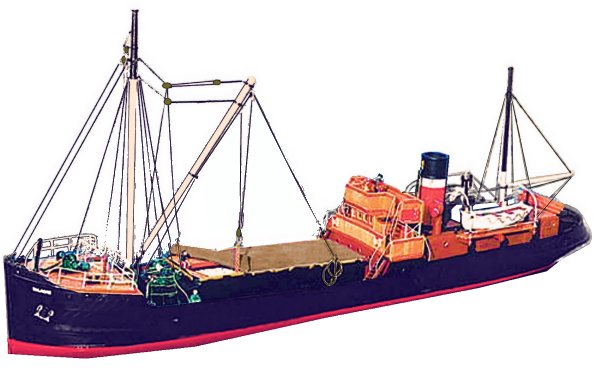
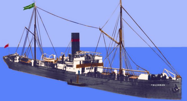
The next size up from the pure coaster was the short sea trader, operating between Britain and Ireland and across to ports on the continent. The Talacre shown below is a typical short sea trading vessel able to take about 300 tons of cargo, these ships were generally 100-150 feet (30-45m) in length (a size determined by the ports and harbours they served).
Fig ___ Short sea trading vessel
Coastal shipping, vessels that ranged around the British coasts and occasionally ventured across the the continent, ranged in size from about fifty tons up to a couple of thousand tons or so. Some quite small sailing barges made it across to Europe and back. For modelling purposes the upper limit would be about the one thousand ton mark, anything bigger starts to take up a serious amount of room. Having said which a lot of ships, although long, were very narrow. The example below is a steam cargo ship of about 2000 tons and dates from the 1890s. A model would be roughly 2 ft (60cm) long in British N, but only three inches (7.5cm) wide, a ship of this size could comfortably manage trips to as far away as Spain and may well have ventured a lot further. The long 'pennant' flag on the after mast is the company flag, many ships fly these on entering port, the ship is picking up the pilot (boarding by 'pilot ladder' a rope ladder with wooden steps) from the small launch alongside. The ship has an open bridge, she is steered from the top of the accommodation block and has a metal frame over which canvas can be secured in bad weather.
Fig ___ Steam cargo vessel of 2000 tons
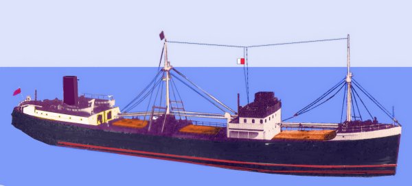
Steam ships of this general type remained in regular use into the Second Word War but disappeared rapidly in the 1940s. The motor ship, fitted with diesel engines, had increased in popularity from the later 1920s and by the mid 1930s it was increasingly the norm for new buildings. The example shown below is a typical later 1930s motor coaster and scales out at eighteen inches by three inches in British N scale, although large this is just about acceptable on the typical home layout. A ship of this type could carry nearly as much cargo as the rather larger steam type shown above. The red and white flag (the H signal flag) indicates that she has a pilot on board and is proceeding under his guidance, this ship has a wooden wheelhouse, offering protection for the man steering the ship.
Fig ___ 1930s motor cargo vessel of 1000 tons
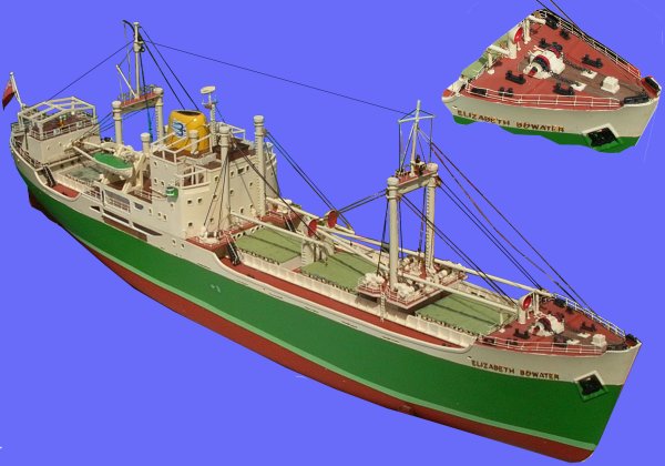
A more common layout was the centre-island type of ship, with the engines in the centre of the ship (although this did require a long shaft tunnel from the engne to the propeller). The example shown below would serve for a period from the mid 1930s to about 1990, although the radar mast just in front of the funnel dates this example to the post war period 1949-1960 or thereabouts. The model shows was photographed at the Astle Park steam rally in 2007 (I made a note of the builders name but then lost it, if anyone knows I would appreciate an e-mail), in British N scale a model of a similar ship would run to about 20 inches in length.
Fig ___ 1940s-1980 motor cargo vessel of 1500 tons
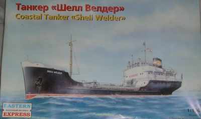
There are a number of models available that can be used for an N Gauge scene, of particular value for post war layouts is the Eastern Models (formerly Novo and originally Frog) Shell Welder. This is a small coastal tanker to something close to N scale.
Fig ___ Kit of the Shell Welder coastal tanker
My own model is currently in storage, the photo below was taken at a stand run by the Manchester Model Boat Club at a steam rally in about 2002, it shows a larger scale model of the same ship, with the old Frog model beside it. The level of detail is similar on both. Unfortunately I cannot credit the builder as their name was not displayed on the stand.
Fig ___ Model of the Shell Welder coastal tanker
The prototype was converted into a bulk carrier (for coal, iron ore etc) and the model can be easily modified into a similar vessel as well as various styles of coastal general cargo ship (see also Lineside Industries - Canals, Docks, Harbours and Ship Types). The model is only produced at intervals, the molds are getting old, but well worth having if you model in N.
Ship Flags and Markings
Every ship has her name painted to either side of the bows and also across the stern. Also on the stern will be the name of the port at which the vessel is registered (all ships have to register with a 'home port' for legal reasons). Fishing vessels are slightly different, carrying a code on their side which indicates their home port, however larger fishing boats could turn up anywhere to unload or repair so if you only have one it could use any of the codes).
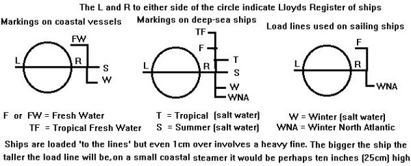
Every ship has 'draught marks' at the bow and stern, these are a vertical series of numbers that show how deep the ship is in the water. Also every ship is required to have a 'load line' marking on her side, indicating at what depth she can safely be loaded to before putting to sea. These are usually called the Plimsol Line as it was an MP by that name who pushed through the legislation to have them applied.
Fig ___ Ships load lines
A ship will always fly the flag of the country in which she is registered (for most countries this is the same as the national flag), on smaller ships this is normally flown on a short post at the stern of the vessel. On larger ships it is sometimes flown from the after mast (where a suitable halyard can be rigged) when entering or leaving port. Some ships flew the company flag from the foremast when entering or leaving port, barges usually had a pennant, a long thin flag the end nearest the mast being rigid with a cloth tail, fitted to the top of the mast and used for gauging wind direction and speed.
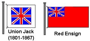
In Britain the Red Ensign was established as the standard flag or ensign for the British merchant fleet in 1867. Prior to this the Royal Navy had used Red White and Blue Ensigns, each fleet being subdivided into three squadrons, each with their own ensign. The system then altered with the white ensign being retained by the Royal Navy, the red ensign being used by merchant ships and the blue ensign was reserved for ships carrying a proportion of Royal Navy Reserve officers in their crews. The blue ensign is also used by a number of organisations who add their own symbol to the 'fly' (the outer part of the flag), for example Army ships have a blue ensign with crossed swords and some yacht clubs use the blue ensign with their club badge on it. Before the introduction of the 'Red Duster' British merchant ships, if they bothered at all, flew the Union Jack, a small square version of the British Union Flag (which dates in its present form from 1801 and should not be called a Union Jack) with a white border. For many years now any British ship of over fifty tons deadweight has been required to fly the British merchant flag by law, hence these flags are seen on coastal ships visiting ports in their own country but seldom if at all on barges.
Fig ___ Ensigns used on British ships
Foreign ships visiting a port always hoist the local national flag, called a 'courtesy ensign', on small ships this is usually hoisted on the fore mast, on larger ships on the signal mast above the wheelhouse.
Small ships calling at British ports, prior to the late 1970's, would probably have been British registered and would have the red duster on the stern. Foreign coastal vessels were relatively uncommon at British ports prior to the 1970's but the occasional Dutch, Belgian or German coaster might be seen and the channel ports might see the odd French vessel alongside. Most countries use their national flag as their merchant ship ensign, India and Pakistan adopted the red ensign design, using their national flag in place of the union jack. Up to the 1960's the British Merchant Navy was easily the largest in the world but the Greek shipping industry was working hard at the low cost end of the market and had become a serious contender in the field by the 1940s.
Fig ___ Ensigns used on Foreign ships
The main factor eroding Britain's dominance of the shipping world was however the so called 'flags of convenience'. These denote ships registered in countries with regulations which allow the ship owner to save money (employing cheap multi-national crews etc.). Flags of convenience first appeared following the shipping depression in 1920-30 but the real growth in this practice occurred after the Second World War when the Americans (who faced very high crewing costs) paid Greek and Italian shipping companies to buy up war-surplus tonnage and register the ships in Liberia, Costa Rica, Panama & Honduras. Hence from the 1970's sea-going vessels might well be registered in one of these countries and would have that countries national flag at the stern.
Fig ___ Flags of Convenience
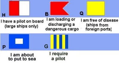
Signal flags are hoisted to pass messages to other ships or to shore authorities and remain in use today. The present system of coded signals was devised in the mid 1930s and revised in 1969, however I believe several of the standard flag signals date back much further. A ship which has a pilot on board would have the H flag hoisted and ships carrying, loading or discharging dangerous cargoes, such as oils and explosives, should have a small red code 'B' flag (square with a triangular indent on the fly, this shape is called a burgee). The B flag was usually also flown by barges carrying dangerous cargo. A ship with a pilot on board and carrying dangerous cargo would fly both the H and B flags. Ships arriving from a foreign port would also have the yellow Q flag, indicating that they have no one on board suffering from any disease. If they know or suspect they have a diseased individual on board they signal (certainly from 1969 onwards) is QQ (two Q flags hoisted one above the other). When a ship made ready to sail she hoists the P flag, known as the Blue Peter, which the code book defines as 'Repair on board I am about to put to sea' although in practice the crew would almost certainly know this and the flag was probably more to do with informing shore authorities and possibly other shipping which might be maneuvering or coming in to anchor in close proximity. To request a pilot the signal is the G flag, hoisted when approaching a port or as part of the preparations to sail.
Fig ___ Some useful ships code flags
Ships radio and radar equipment
All ships had some form of radio equipment by the 1950's, by the 1960's a standard piece of equipment was the VHF radio-telephone. These have white antennas which resembles a three foot length of broom handle, supported near the base by one or two metal clamps. Larger ships, and quite a few coastal vessels, would have some form of Medium Wave or MF radio equipment, this would involve a couple of wire antennas at least twenty foot long with white insulators on the ends. By the 1970's fibreglass 'whip' type antennas were favoured for MF by smaller ships, replacing the suspended wire type, these would be white, slightly tapered and about twelve foot long, again supported at the base by metal clamps.
Radar only appeared on smaller ships in the 1970's, early designs used a semi-circular antenna, often painted red, but by the 1980's these were rare and the white solid bar type was the norm. The scanner would be about six inches wide and two or three inches high by perhaps four foot long on a small ship, anything up to ten foot long on a sea going vessel. By the 1970's it was usual to mount the radar scanner on a bracket on the front of the 'signal mast' which is the mast located close by the navigating bridge up which the signal flags are hoisted.
Ship Canals
Four 'ship canals' were dug in Britain, the nine mile (14.5 km) long Crinian canal does not connect with the canal network, it simply provided a shorter route than sailing all the way round the Mull of Kintyre. The three remaining ship canals were provided allowing ocean-going vessels access to inland areas, bear in mind however that sea going and even ocean going ships were rather smaller than today. Wooden hulled ships were constrained by the properties of the wood, they could not be built very large and a big 'ocean going' sailing ship only weighed in at about 500 tons. The use of iron and steel, first for the ribs and later for the entire hull allowed much larger ships to be built. The use of steam power was also a major factor as the force required to drive a ship through the water is proportional to the square, whereas the tonnage carried is proportional to the cube, hence in shipping bigger is very much better where economy is concerned.
The oldest ship canal in Britain is the Gloucester-Sharpness ship canal, linking the once important inland port of Gloucester with the estuary of the river Severn. Built in the 1790's to eliminate some of the more convoluted stretches of the river this was a success and remained in use into the 1970s (although by the 1960's it was mainly used by small coasters carrying petroleum up to Gloucester docks).
The Caledonian Canal was the last great project of the Canal Age, the only canal to be funded by public money it was intended to kick-start the development of industry along the central 'great glen' of the Scottish highlands. Completed in the first decades of the nineteenth century by Thomas Telford it ran from Inverness to Fort William and opened in 1822. Interconnecting a series of lakes on the route the Caledonian Canal linked the Atlantic and North Sea coasts, allowing ships to avoid the long voyage round the north of Scotland. The only problem was that the locks were designed to handle the wooden hulled sailing ships of the later 18th century, hence most of the new and larger iron and steel hulled steam ships were too large for the locks after about 1900. To speed up construction the canal had accepted lower standards of work, so the locks had problems and even the smaller ships tended to avoid using it and the project was a financial failure.
Fig ___ Caledonian Canal
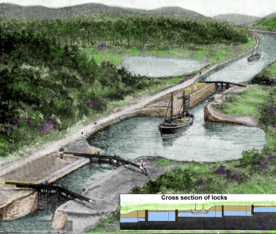
The sketch below (based on an illustration in a book from the 1930s) shows a typical lock on such a canal, there is a reservoir (to the left of the canal in the picture) and between the two locks is a basin to allow ships to pass, saving water. The stretch of canal in the upper part of the picture is the 'upper reach', the lower level toward the bottom of the picture is the 'lower reach'.
Fig ___ Lock on a Scottish Canal
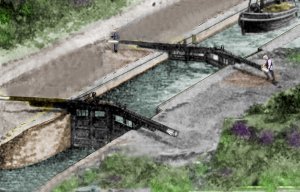
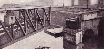
The most famous British ship canal is of course the Manchester Ship Canal, which linked central Manchester and Salford with the Mersey Estuary. Built in the first decade of the nineteenth century the ship canal passes under the original Bridgwater Canal and the latter had to be provided with a 'swing aqueduct', a steel channel fitted with sluices and mounted on a pivot standing on an island in the ship canal.
Fig ___ Barton aqueduct in use in the 1920s
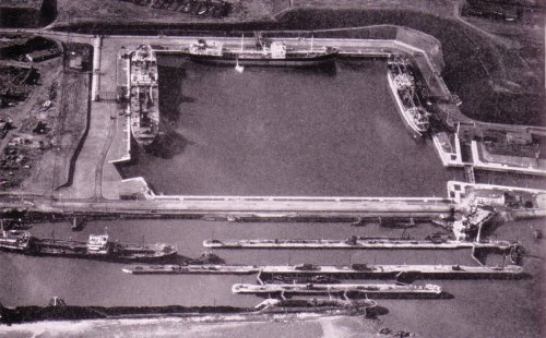
The photo below is a publicity photo released by the canal company in 1955 shows the entrance to the canal in about 1955, the oil terminal in the upper part of the photo (able to take up to four 30,000 ton tankers and considered big at the time) was opened in 1954 (replacing smaller oil berths dating back to the 1920s).
Fig ___ Locks at the entrance to the MSC
Manchester docks became the fourth most important in the country, after London Liverpool and Southampton with imports including raw cotton, timber, grain, metals and chemicals, and massive amounts of manufactured goods being exported in return. Oil traffic had also become important, with Shell and other companies building huge refineries and depots in the Stanlow area.
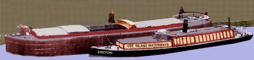
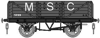
The Manchester ship canal had its own internal railway system with large numbers of small tank engines, quite a lot of goods stock including a number of ex GWR goods break vans and even a few coaches. The railway served and connected a large number of industries alongside the Ship Canal and around the dock complex in Salford. The ship canal internal railway was closed down in 1972 but sections remained in place within the various docks and rolling stock was left in place to service these isolated sections. In one area a small fleet of old container flat wagons and bogie bolster wagons was retained to move steel sections to and from the ships sides.
Manchester Ship Canal open wagon
Manchester Liners was established in the 1890s following reluctance on the part of Liverpool shiopowners to trade to Manchester. The company traded from Manchester to Canada, the USA and ports in the Mediterranean and was an early adopter of the ISO standard container, its first purpose built container ship (Manchester Commerce) entering service in 1963. This was the first of a fleet of five ships, all 502 feet long dual purpose container and general cargo ships with the superstructure mounted aft to give a clear area for the containers. In 1968 purpose built container cranes were installed at a new container terminal at Salford No 9 dock, served by a fleet of 'straddle carriers' but more conventional cranes were also used where the boxes were being loaded onto non-container ships (such as coasters, who in those days often carried a few containers as deck cargo). The line introduced modern 'cellular' container only ships in 1971 (starting with Manchester Quest and Manchester Concept), around this time they established a liner service to Iran. Sketches of the Manchester Liners container liveries have been included in the section 'Unit Loads - Modern Containers, Road Railer, Piggyback and Swap Bodies'.
Manchester liners was bought out by C. Y Tung in 1982 and as the trend was for ever larger ships the upper part of the canal, limited to ships of about 10,000 tons, went into a rapid decline. The upper part of the canal feeding Trafford Park in the city itself was closed in the mid 1980's but the lower reaches are still used by smaller oil tankers and gas carrying ships feeding the Shell berths at Stanlow (built in 1922 and 1933).